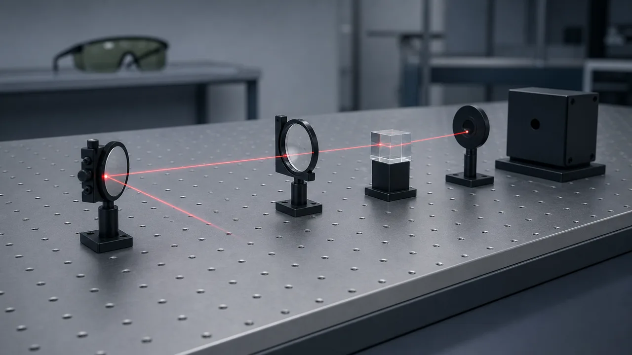
Photos of laser labs tend to show the same things. A wide table covered in a grid of small threaded holes. Rows of little holders standing on it, gripping mirrors and lenses.
A round sensor at the end of the beam. Glasses with colored lenses hanging on the wall.
The equipment in such photos falls into five groups. They are the table that acts as a floor, the parts that hold things, the parts that handle light, the instruments that measure light, and the gear that protects people. The sections below follow that order and explain what each item is and why it is there.
The lab photo, item by item
A laser itself has three parts, as The three parts of a laser shows. A medium amplifies the light, a pump feeds in energy, and a resonator keeps the light bouncing. A lab holds far more equipment around that laser. The drawing below gathers items that show up often in lab photos onto one table.
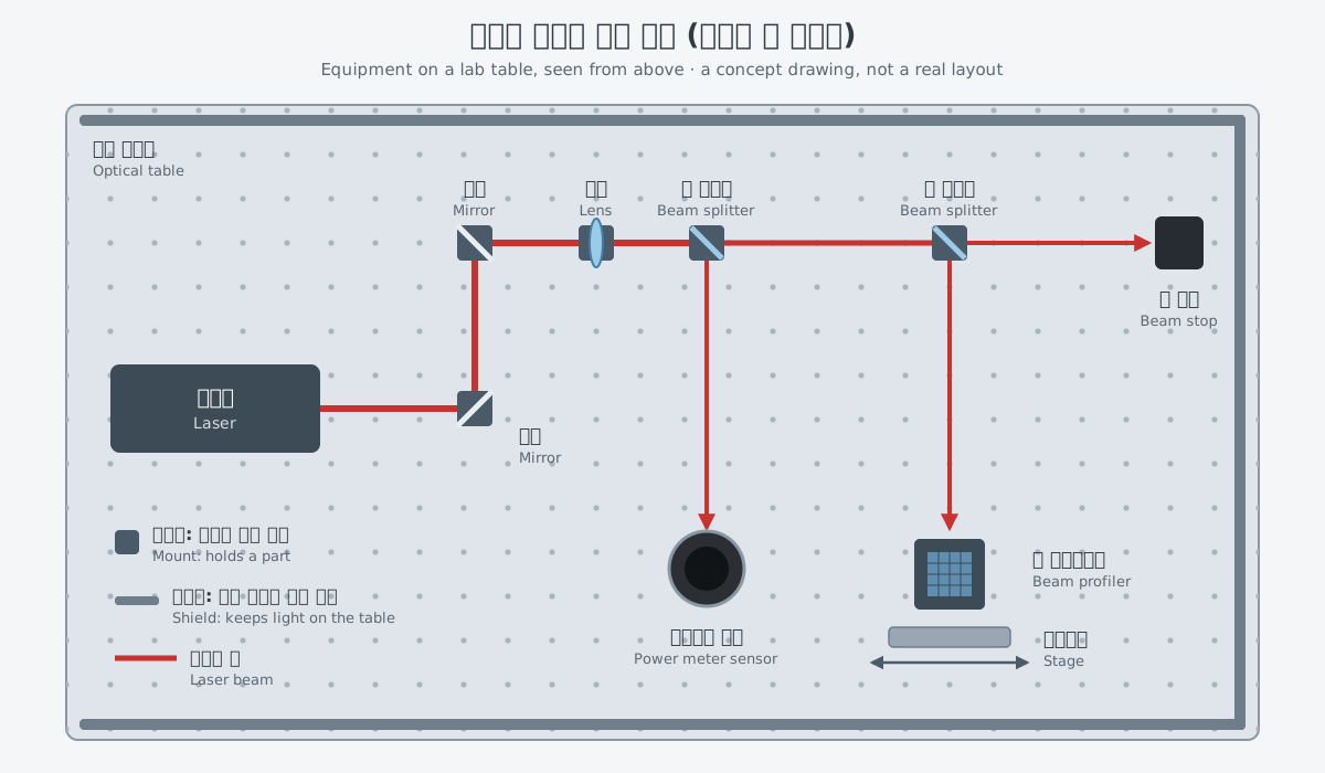
| Item | What it does |
|---|---|
| Optical table | A floor that ties the parts together so they do not shake against one another |
| Mount | A holder that grips a mirror or lens and lets its tilt be changed in small steps |
| Stage | A device that moves a part along one straight direction |
| Mirrors and lenses | Parts that send light back or let it through, changing where the beam is narrowest and how wide it is there |
| Beam splitter | A part that splits one beam of light in two |
| Optical power meter | An instrument that measures the power of a beam |
| Beam profiler | A device that measures how light is spread across the beam |
| Eyewear, beam stop, interlock, shields | Gear that protects people's eyes and skin from the light |
The items in this table fall into two groups. Some items build the path the light travels. The rest keep that path from shaking and keep the light away from people. The sections below take them one at a time.
The optical table: a floor that does not shake
An optical table looks like a large, heavy steel table, but its job is harder than it looks. Vibration can limit the performance of a wide range of research and production work. Some background vibration is always there, from building air-handling equipment to road traffic, and it cannot be avoided.
The real problem is not shaking as such but parts moving differently from one another. Think of taking a photo of a highly magnified image. If the light source, the sample, the lenses and the camera all move together in exactly the same way, the image stays sharp. If the sample moves even slightly relative to the objective lens, the image blurs.
The same thing happens inside a laser. When the mirrors of the resonator vibrate, they can add a large share of phase noise to the laser light unless the resonator is built to be very stable. If a mirror tilts, the resonator goes out of alignment. Mechanical stability matters for getting low-noise light from a laser.
The sources of vibration cannot be removed completely. So an optical table ties the parts together with a structure that is as rigid as possible, which cuts the relative motion between them. Rigidity, the ability to resist bending under force, is the first thing considered in optical table design.
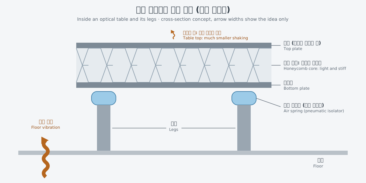
Inside many optical tables is a honeycomb core. Honeycomb is a common way to build structures that are very light yet very stiff. Less weight pushes the frequencies at which the structure resonates higher, where they do less harm, and the table bends less for the same vibration force. A Newport technical note gives this as the main reason steel honeycomb has replaced heavy granite in most high-end optical work.
Stiffness alone is not enough. Once the table starts to ring, damping makes the ringing die down and reduces the relative motion across the table surface. In very precise work such as optical interferometry, this damping is especially important.
The legs have a job too. Air springs in the legs, called pneumatic isolators, filter out floor vibration before it reaches the table top. This is a bit like a car's suspension, which passes fewer road bumps to the body.
There is a real difference. An air spring does not block every shake: vibration slower than its natural frequency passes through almost unchanged, and at the natural frequency, vibration is actually made larger.
Temperature is another source of movement. In the same technical note, uneven temperature changes usually bend the structure slowly, over an hour or more. This is one reason labs try to keep the temperature steady.
Systems used outside the lab bring other conditions. One company that builds high-power laser systems designs the optics placed after the laser, such as beam expanders, with environmental conditions in mind. It names temperature stability, contamination control and mechanical robustness. For a picture of such a system as a whole, see A laser weapon is more than a laser.
Mounts and stages: holding and moving the parts
In any optical system, each optical element must be mounted in some way. The rows of small holders on the table in a lab photo do that job.
A mirror mount holds a mirror firmly while letting its tilt be changed, up and down and side to side, in very small steps. Mounts are usually fixed to the optical table, so they share the table's vibration isolation. The ways of changing the tilt include kinematic, gimbal and flexure designs, and the kinematic type is by far the most common.
A stage moves a part. A linear translation stage keeps motion on an ideal straight line. Any unwanted motion in the directions it is meant to hold steady pulls the part off its path or away from the spot where it should stop.
Mounts and stages both have to allow movement while staying steady. Meeting those two demands at once, which seem to pull against each other, is what these small devices are for.
Optical components: mirrors, lenses, beam splitters
A laser beam often travels through an optical system made of lenses, mirrors, dielectric interfaces and other optical elements. A mirror is a part that sends light back, and a lens is a part that lets light through. Such optical elements change the position and size of the beam waist, the spot where the beam is narrowest.
A thin focusing lens is probably the most important optical element affecting a laser beam. Why a beam spreads and comes to a focus is covered in Why a beam spreads.
A beam splitter is a part that splits one beam of light in two. It is used when one beam has to go to two places. On the table in the first drawing, two beam splitters divide the light. One branch goes to the power sensor, and the other goes to the device that measures the beam's shape.
What parts that handle strong light have to withstand, including their surface coatings and damage thresholds, is covered in Mirrors, lenses and coatings.
Instruments that measure light
The eye cannot tell how strong a laser beam is. So an optical power meter sits at the end of the beam. Its sensor turns the light into an electrical signal, and the meter amplifies that signal and shows the power received. There are two main kinds of sensor.
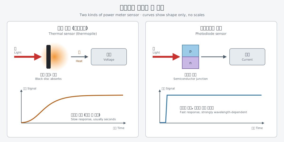
A thermopile is a thermal sensor based on thermocouples, junctions of two different metals. The laser beam is absorbed by the sensor's disc and becomes heat, and the temperature difference across the disc produces a voltage. One power meter manual says this voltage is proportional to the incoming power.
Because the disc takes time to heat up and cool down, the response is slow, usually on the order of seconds. So thermopiles are used to measure the power of continuous-wave (CW) or nearly continuous sources.
A photodiode sensor measures light directly at a semiconductor junction. Light absorbed at the junction creates charge carriers. Most photodiodes are run with a voltage applied across the junction in reverse, and the current they then produce is proportional to the incoming light intensity over a wide range.
Photons turn into electrons very quickly, so the sensor can follow light that changes fast. The trade-off is that its sensitivity depends strongly on wavelength.
The two sensors are good at different things. A thermal sensor turns light into heat and is slow, while a photodiode is fast but depends heavily on wavelength. The difference between continuous and pulsed light is covered in Continuous-wave and pulsed lasers.
Power alone does not describe the whole beam. A beam profiler measures and analyzes the spatial distribution of a laser beam, meaning where across the beam the light is concentrated and by how much. This measurement is essential for knowing how intense the light is where it is used, and it can also reveal problems in the beam.
Beam profilers come in several types. A camera-based profiler catches the beam on an array detector, a dense grid of small sensors, and shows the beam's cross-section as a two-dimensional picture. A scanning-slit profiler moves a narrow slit across the beam and catches the light that passes through on a single detector, rebuilding the beam's shape. Camera profilers show fine structure and unusually bright spots in the beam, while slit profilers usually measure beam size more accurately and can measure very small beams directly.
Every profiler has a sensor, so light that is too strong can saturate or damage it. That limits how much laser power can go in, and a strong beam is reduced before it reaches the sensor.
Safety equipment
The last group of lab equipment is there for people, not for the light. The safety of laser products is also set out in an international standard. IEC 60825-1, from the International Electrotechnical Commission (IEC), applies to the safety of laser products that emit laser radiation in the wavelength range from 180 nm to 1 mm.
The most visible item is eyewear. The laser safety handbook of The University of Texas at Austin (UT Austin) says laser protective eyewear must match the type of laser radiation in that lab. The factors for choosing it include the laser's wavelength and the optical density (OD) at that wavelength. Conditions such as maximum power and whether the laser is continuous or pulsed also count.
Eyewear also wears out and gets damaged, so it needs regular inspection. How to read the wavelength and OD printed on eyewear is covered in Laser safety: classes and how to read eyewear labels.
A beam stop is where a beam ends. The safety handbook says laser beams should be terminated in a suitable beam stop. A beam stop that does not reflect light and does not catch fire lowers the risk of accidental exposure and of fire. Extra beam stops can also be placed along the beam path to keep the useful beam inside the experimental area.
An interlock is a device connected to the laser that turns the beam off or reduces it when something happens, such as a door opening. In the laser safety class names used by the UT Austin handbook, protective housings of Class 3a, 3b and 4 lasers should be interlocked. For Class 4 lasers with open beams, the US ANSI standards call for interlocked doors or devices. These turn off or reduce the beam if someone enters unexpectedly.
The laser safety article mentioned above notes that there is more than one system of class names.
The panels standing along the edges of the table are safety equipment too. Shields and barriers around the laser work area keep the beam, its reflections and scattered light on the optical table. The optical table is a floor that resists shaking, and it is also the boundary where the light has to stay.
What to read next
- "Pump diodes: the part that turns electricity into light": the part that feeds energy into a laser.
- "Measuring light: power meters, beam profilers, spectrum analyzers": a closer look at the instruments touched on here.
- "Vibration and shock: protecting optics on a moving platform": shaking outside the lab.