A laser holds several optics: mirrors that send light back and parts that let light through. When the power goes up, what these parts go through changes too. In one experiment, the spot where the beam hit a mirror heated up, and that ended in damage.
So the optics in a high-power laser are not chosen only for how well they reflect. This article starts with what a coating, a thin layer laid on the surface of an optic, actually does. It then looks at stacked-layer laser mirrors, coatings that cut reflection, absorption and heat, and the damage threshold test that measures how much an optic can take.
When light meets a surface: reflection and transmission
Light that reaches an optic does not take just one path. Part of it bounces back, part of it passes through, and the optic keeps a share. The first two are called reflection and transmission, and the last one is absorption.
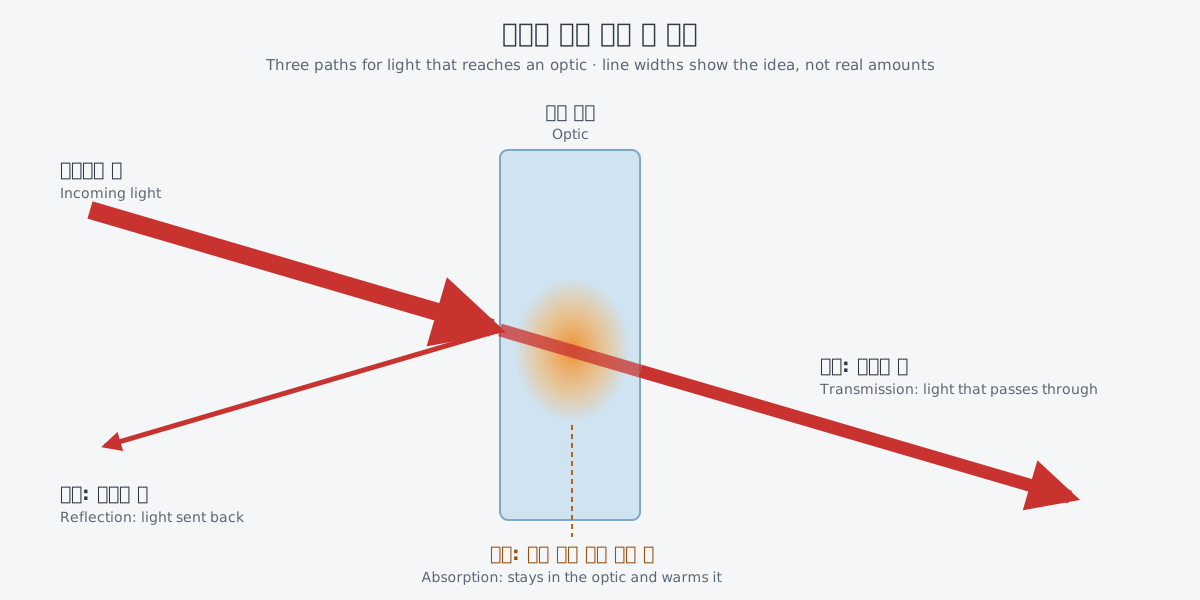
A look inside a laser mirror shows where reflection comes from. A standard high-reflectance laser mirror is a stack of alternating high-index and low-index layers, and every index step between two layers gives a Fresnel reflection. As Light basics showed, the refractive index is tied to how fast light travels in a material. At such a boundary, incoming light splits into a reflected beam and a transmitted beam.
In this article, lenses appear as one example of an optic that light passes through, and in the name "thermal lens," which heat creates. How a lens gathers light continues in "Why a beam spreads."
Coatings: thin layers that change reflection
How much light an optic sends back and how much it lets through can be changed with thin layers on its surface. A NASA report on damage threshold testing gives a definition. An optical coating is "material deposited in single or multiple layers onto an optical substrate that is designed to alter the reflective or transmissive properties of the optic." The substrate is the base part that the coating sits on.
One textbook figure of laser pumping schemes labels the faces of the parts HR (high reflection), HT (high transmission) and AR. AR stands for anti-reflection coating. The same part can have a face that sends light back or a face that lets light through, depending on the layers put on it.
Stacked-layer mirrors: the Bragg mirror
A standard high-reflectance laser mirror is a Bragg mirror. It is a stack of layers with alternating high and low refractive index. This mirror reflects the most at one set wavelength, called the Bragg wavelength. Each layer is a quarter of the Bragg wavelength thick.
A high-reflectivity coating with almost no dispersion, the effect that stretches a pulse, typically consists of a stack of dielectric quarter-wave layers. Such a stack also goes by the names Bragg reflector and distributed Bragg reflector (DBR).
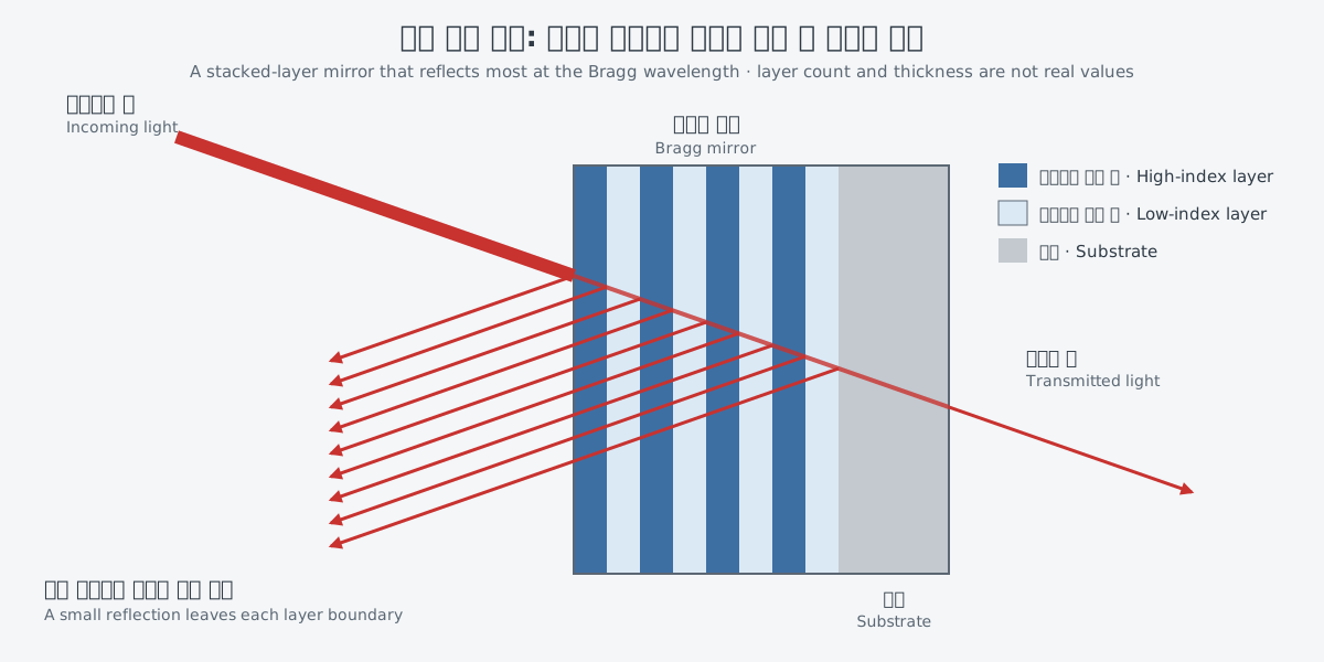
Each boundary between layers is an index step, so a small reflection leaves every boundary. It is a bit like several glass panes standing one behind another, each showing a faint reflection of your face.
The real thing differs in two ways. Each layer is not a pane but a thin film a quarter of the Bragg wavelength thick. And the stack does not give many faint reflections: it becomes a high-reflectance mirror that reflects most at the Bragg wavelength.
The reflectivity spectrum of a Bragg mirror has a range of wavelengths with high reflectivity. This range is called the stop band, and at its edge the reflectivity drops off sharply. Well within the stop band, a pulse is reflected without distortion. But this changes sharply once the range of wavelengths in the pulse extends beyond the stop band.
Interference and diffraction covered some mirrors, such as dispersive mirrors, that use interference effects. Some stacked-layer mirrors are made to handle pulse dispersion in this way. One of them, the GTI-type mirror, has a more complicated thin-film structure than a standard Bragg mirror.
Anti-reflection coatings: layers that cut reflection
If some layers raise reflection, others lower it. An AR coating is, as its name says, a coating laid on to cut the reflection from a surface. In the pumping-scheme figure mentioned above, the AR labels also sit on the faces of laser parts.
Still, an AR coating does not remove reflection completely. The small reflection that remains is called residual reflection. When an AR coating is used with a stacked-layer mirror, the trouble is whether this residual reflection interferes with the multi-layer stack beneath it. If it does not, the limit on how much residual reflection is acceptable can be relaxed a great deal.
Absorption and heat: strong light warms the optics
A mirror with a more complex layer structure, like the GTI-type mirror above, absorbs more light than a standard Bragg mirror and handles heat worse. Its damage threshold can drop too, and the reason lies in the field of the light. Inside such a multi-layer structure the field can grow strongly, which is called field enhancement. Light is an electromagnetic wave, so the field here means the electromagnetic field that makes up the light.
A large field enhancement raises unwanted nonlinear absorption compared with a standard highly reflective multi-layer stack. As a result, thermal properties get worse, the damage threshold drops, and losses rise. In high-power ultrafast solid-state lasers, this can become a significant issue.
In a thin-disk laser at high average power, scaling up the power also makes the average power on the optics inside the optical resonator very high. Then even simple Bragg mirrors need to be optimized for a higher damage threshold with different coating materials. For example, in one experiment with such a laser, an infrared camera showed stronger heating at the beam spots on a resonator mirror where light makes many passes. This ultimately led to damage.
Optics that absorb light also bring a problem called the thermal lens. In lasers with high average power, the thermal lens of a SESAM becomes an issue. A rotating filter wheel that dims light can also cause thermal lensing at high average power. SESAM stands for semiconductor saturable absorber mirror, a mirror that carries the saturable absorber seen in Q-switching and mode locking.
Damage threshold (LIDT): how the limit is measured
What does it mean for an optic to be "damaged"? The NASA report defines optical damage as a permanent physical change in an optical material that results from interaction with a laser beam. In the test procedure, a permanent change such as pitting or coating delamination counts as damage. The tested optic is examined at a magnification of at least 100x so that no damage goes undetected.
A laser-induced damage threshold (LIDT) test is a destructive test that finds the maximum laser energy density below which no damage to an optical material is observed. This energy density is called fluence, the applied laser energy divided by the cross-sectional area of the incoming beam.
Fluence = laser energy ÷ beam cross-sectional area
If intensity in Power, energy and intensity is power per area, fluence is energy per area. The report covers optical materials used in pulsed-laser systems. Coated and uncoated substrates, laser crystals, Q-switches and polarizers are among them.
A damage threshold value cannot be separated from the conditions that produced it. The test uses a pulsed laser of known wavelength, pulse length, polarization and transverse mode. The report warns that beams smaller than 1.0 mm in diameter artificially increase the damage threshold value obtained with this procedure. The same optic can give a different number depending on the beam used to test it.
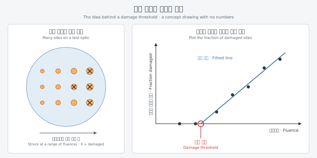
The threshold is not set by firing once at one spot. In this procedure, many sites are struck at several fluences, the fraction of damaged sites at each fluence is plotted, and a straight line is fitted by linear regression. The damage threshold is the x-intercept, where that line meets the horizontal axis. When the testable area is too small for an accurate regression, the highest fluence that caused no damage is taken as the threshold.
What to read next
- "Why a beam spreads: divergence, focus and aperture": follows how a lens gathers light and why a beam spreads.
- "Limits of a single fiber (2): heat and mode instability": looks at the marks heat leaves on the beam in a fiber laser.