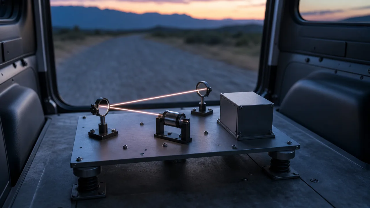
Picture two glasses standing side by side in the back of a truck. As long as they shake together, the gap between them stays the same. Trouble starts when the floor twists, or when one glass alone jolts.
The mirrors and lenses that carry laser light are much the same. A laser in a lab usually sits on an optical table that keeps out shaking. A laser weapon may instead ride on a moving platform such as an aircraft, a vehicle or a ship. A 2010 paper from the Naval Postgraduate School (NPS) counted rejecting the jitter produced by platform vibration among the key technologies for laser communication and high-energy laser systems.
Why is optical alignment so sensitive to shaking? And what are the broad ways to protect optics in a place that shakes?
Vibration and shock came up briefly as causes of jitter in "Gimbals, pointing and tracking: holding the beam on one spot." This article looks at them more closely. The parts that make up a laser weapon are laid out in "A laser weapon is more than a laser".
How vibration differs from shock
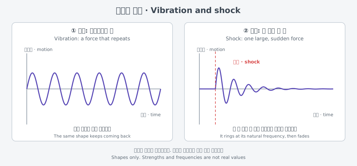
Vibration is shaking that repeats with the same shape. Shock is one large force that arrives all at once. It happens when something hits, or when something held in place is suddenly released.
The shapes differ, but the results are alike. Whether the outside force is a single shock or a repeating vibration, a structure answers by ringing at its own natural rhythm. The spring stores energy and gives it back, over and over.
Hardware headed for space goes through both. NASA's Goddard Space Flight Center sets this out in its General Environmental Verification Standard (GEVS, GSFC-STD-7000B). The standard requires verifying environments such as vibroacoustics, sine vibration and mechanical shock across all phases of the mission, such as launch, insertion into orbit, and entry, descent and landing.
The transportation and handling environments must be checked too. Before hardware ever leaves the ground, it shakes while it is moved and handled.
The same standard gives examples of where shock comes from. Firing pyrotechnic or pneumatic devices to release solar arrays or protective covers is a main source, and so is a deploying device striking the end of its travel. Some shocks come from the hardware itself.
Moving together is fine; moving apart is the problem
Shaking can harm optics in more than one way. A vibration tutorial from Newport (MKS) shows the difference with a mirror mount on a lab table. If the tabletop only moves up and down as one piece, even sensitive systems are not affected. The biggest cause of beam deflection is the tabletop bending.
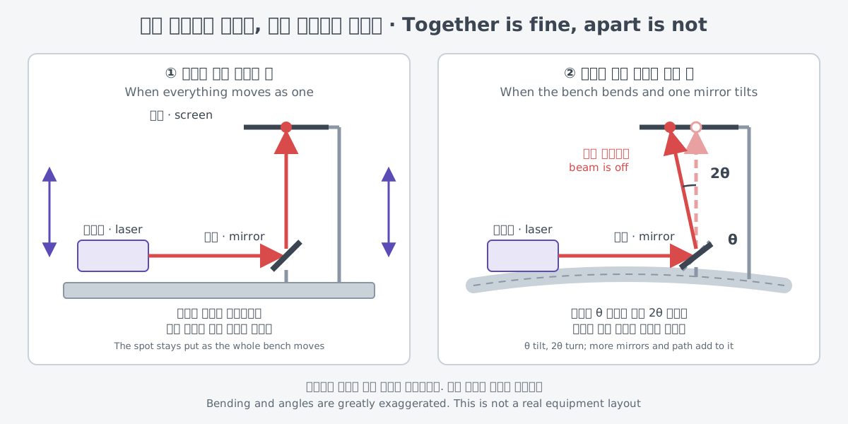
Bending is a problem because of the mirrors. When a mirror tilts, the reflected beam turns by twice the tilt, and the error grows with distance from the mirror. In the tutorial's own example, a flat mirror tilted by just 1 milliradian (1 mrad) shifts the reflected beam by 2 mm at a distance of 1 m. Multiply that by the number of mirrors in a setup and the total path length, and the results can suffer badly.
How the same angle grows at a distance was worked through with a calculation in "Gimbals, pointing and tracking." The point here is what moves. When the mount, mirror and screen move as one block, the beam stays in place. The beam goes off when parts move differently from one another, or when one of them tilts.
This is where the truck-and-glasses picture breaks down. The glasses only need to keep their spacing, but a mirror has to hold a tiny angle, and any error in that angle is doubled.
Even a small relative motion between mirrors and lenses can degrade precision pointing. Cavity mirrors inside a laser are sensitive to vibration and tilt for the same reason, as seen in "Inside a laser lab."
Resonance: the frequency where shaking grows
Every structure has frequencies at which it vibrates easily. Such a frequency is called a natural frequency. In the simplest system, a mass on a spring, the natural frequency is set only by the mass and by how soft the spring is.
ω₀ = 1 / √(C × M)
Here M is the mass, and C is the compliance, a measure of how soft the spring is. A larger mass or a softer spring lowers the natural frequency. A tuning fork for the note "A" vibrates at 440 Hz because it is designed with that natural frequency.
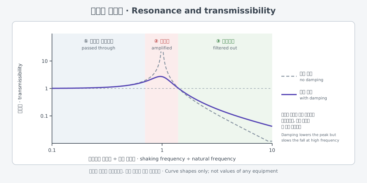
When the base shakes, how much the object on it follows is called transmissibility. It is the ratio of the object's motion to the base's motion. Its value falls into three zones, depending on the shaking frequency.
| Shaking frequency | The object on top |
|---|---|
| Far below the natural frequency | moves exactly like the base |
| Near the natural frequency | shakes more than the base (resonance) |
| Far above the natural frequency | barely receives the shaking |
In the third zone, the spring acts as an isolator that blocks the shaking. The second zone is the dangerous one. With no damping at all, the motion at resonance grows without limit, in theory.
This is where damping comes in. Damping drains mechanical energy from the motion so that vibration dies down faster. More damping lowers the resonance peak.
In exchange, transmissibility falls more slowly at high frequencies. Gaining on one side means giving a little on the other.
Three ways to deal with shaking
The ways to deal with shaking fall into three broad groups: filtering it out, tying parts together stiffly, and measuring it to cancel it. What follows gathers principles from public sources by group. It does not describe how any particular piece of equipment is built.
The first is filtering out. Setting optics on a soft mount lowers the natural frequency, so shaking much faster than that frequency gets through less. That widens the third zone in the table above. Shaking slower than the natural frequency still passes through, though, and shaking near it is even amplified.
The second is tying parts together stiffly. No real structure is perfectly rigid; every structure vibrates by flexing and twisting. The softer a structure is, the more easily the same force moves it. Binding the parts that must hold their angles to one another into one stiff block cuts down the "moving apart" seen earlier.
The third is measuring and cancelling. When shaking cannot be kept out, it can be measured and countered by moving the other way by the same amount. In the NPS high-energy laser beam control testbed, signals from gyros, which measure rotation rate, stabilize the telescope gimbal against outside disturbances.
The paper notes that in this testbed, on-board sensors such as rate gyros are typically more accurate than the video tracker for measuring platform disturbance. Fine tracking and pointing of the beam are handled by a camera and a fast steering mirror (FSM).
This testbed uses a low-power laser to keep the lab safe. It does not show how a real weapon is built; it is a lab study of the measure-and-cancel idea.
The three do not replace one another. Filtering is strong against fast shaking, a stiff block cuts misalignment between parts, and measuring and cancelling takes care of the shaking that gets through.
Proving it by test
A claim that hardware withstands shaking has to be shown by test. The NASA standard requires that all subsystems and instruments of space hardware be qualified for the mechanical shock environment.
Sometimes the test itself can harm the hardware. Some hardware contains delicate optics, detectors or sensors that could be damaged by the test levels in certain frequency bands. For such hardware, the levels in those bands may be reduced with project concurrence. Hardware with optics inside needs its test levels chosen with care as well.
Companies highlight environmental testing too. FiberBridge Photonics, which develops and manufactures laser systems, says it offers environmental testing to customers in sectors that include space and defense. It says it follows industry standards such as the Telcordia Generic Requirements and MIL-STD-810H. The conditions it names include temperature changes, vibration and shock.
Lasers on moving platforms
Aircraft are a long-standing example. The previous article showed that jitter control, which keeps aircraft vibration in check on the Airborne Laser (ABL), was still a risk in 2010.
On an aircraft, vibration is not the only thing that shakes the beam. A U.S. Air Force research topic released in May 2025 covers a beam director that sends a high-energy laser from a flying platform. It says the beam director must compensate for all relevant aero-effects to keep jitter low.
There are lasers on ships, too. Describing the U.S. Navy's shipboard laser development plan, Congressional Research Service (CRS) report R44175 notes that one of its efforts, the Ruggedized High Energy Laser (RHEL), is now completed. The report does not say what was made rugged.
On ground vehicles, the gap between the lab and the field has shown. According to press reports cited in CRS report R46925, in February 2024 the U.S. Army sent four Stryker-mounted DE M-SHORAD prototypes to the Middle East for soldiers to test. Early soldier feedback was described as "not overwhelmingly positive," and officials said results from the lab and test ranges are very different from the tactical environment. The report does not give the cause of that difference.
What is still hard
Shaking does not only come from outside. The list of jitter sources in the previous article also includes heating and cooling systems. Equipment that a system carries with it can make it shake, too.
Working it all out in advance is hard as well. How a tilted cavity mirror affects a laser depends on the cavity design. It also depends on factors such as the pump distribution and thermal lensing in the gain medium, so a general quantitative description becomes very difficult.
Filtering, stiff binding, and measuring and cancelling each handle a different kind of shaking. Keeping a beam steady on a shaking platform means making all three work together.
What to read next
- "Fast steering mirrors: small, quick mirrors that cancel shake": a closer look at the fast steering mirror at the heart of measuring and cancelling.
- "Gimbals, pointing and tracking: holding the beam on one spot": jitter, gimbals, and the calculation of how a small tilt grows at a distance.
- "Inside a laser lab: from the optical table to the power meter": the optical table that keeps shaking out of a lab.
- "Cooling and thermal management: where the heat that did not become light goes": the cooling equipment that also appears on the list of shaking sources.
- "A laser weapon is more than a laser: the system at a glance": where the optics in this article sit in the whole system.