Can a laser work without mirrors? Every laser needs an optical resonator that sends light back through the gain medium again and again, and usually two mirrors do that job. In a high-power fiber laser, though, the preferred design does not mount those mirrors outside the fiber. It writes them into the fiber itself.
The mirror written inside the fiber is a fiber Bragg grating (FBG). It looks like a plain strand of glass, yet it picks out one color of light and sends it back. This article follows how it works, its history starting in Canada in 1978, its two main jobs in fiber lasers and in sensors, and its limits.
The basic idea, that an FBG is a filter that returns one wavelength, came up briefly in Isolators and fiber components: keeping light from going backwards. This article goes one step further inside.
A mirror that sends back one color
Start with an ordinary laser mirror. A standard high-reflectance laser mirror is a Bragg mirror. It is a stack of thin layers that alternate between high and low refractive index, and each layer has an optical thickness of a quarter wavelength.
This mirror does not reflect every color equally. One wavelength gets the strongest reflection, and that is called the Bragg wavelength. Over a range around it the reflection stays high, then drops sharply at the edges. That range is called the stop band.
Why only one band? In a medium whose refractive index rises and falls at a regular spacing, light whose wavelength matches that spacing couples to light going the opposite way and is sent back. This matching condition is called the Bragg condition. More on how stacked mirrors handle reflection is in Mirrors, lenses and coatings: optics for strong light.
Stripes inside the core
A fiber Bragg grating moves this idea inside a fiber. In its simplest form, an FBG is a section where the refractive index of the core of a single-mode fiber has been changed permanently at a regular period. This pattern of index along the fiber sets the reflection and transmission spectra.
It differs from a thin-film mirror in two ways. First, nothing is stacked. The index simply changes in stripes inside the same glass core.
Second, the index difference between stripes is small. Keller's ultrafast laser textbook notes that the calculation method suited to small index steps has typically been used for fiber gratings.
The wavelength sent back is the Bragg wavelength. It is set by the grating period, which is the stripe spacing, and by the effective refractive index that light feels inside the fiber. The grating period is usually close in size to the wavelength the grating works at. For that reason, Exail's technical note says making the grating is very sensitive to environmental conditions.
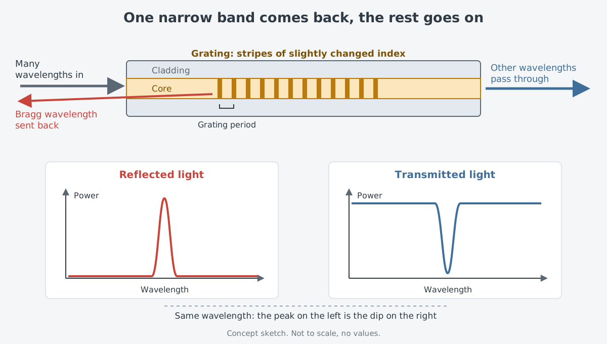
A kitchen sieve gives a feel for the job. A sieve sorts by size, and a grating sorts by wavelength. In practice the two work the other way around. A sieve keeps what it catches and lets the rest fall through, while a grating sends back only the narrow band it picks and lets almost everything else pass.
How the pattern is drawn changes the grating's character. Types of FBG are told apart by the profile of the index modulation written into the core. The common ones are:
- Uniform: stripes of the same strength and spacing. It is the simplest, but it does a relatively weak job of suppressing the side lobes next to the main peak.
- Apodized: the stripe strength follows an envelope, such as a bell shape. Side lobes are well suppressed, reflectivity is high and the band is narrow.
- Chirped: the grating period changes along the length. It is designed to reflect a broader band than a uniform grating.
The manufacturer's note lists the pi-shifted grating as a common type alongside these three.
Chirping shows up in thin-film mirrors too. In a chirped mirror, the Bragg wavelength changes from place to place, which widens the high-reflectance range compared with an ordinary Bragg mirror. In a fiber grating, that change comes from the stripe spacing rather than from layer thickness.
The uses are wide. In its technical note, Exail lists wavelength division multiplexing (WDM), gain flattening filters, dispersion compensation, fiber lasers, frequency stabilization of DFB and Fabry–Perot lasers, and acoustic, strain and temperature sensing. The same note describes the FBG as a low-loss filter that leaves designers a lot of freedom.
It began in Ottawa in 1978
The story starts at the Communications Research Centre Canada (CRC), a government agency. In 1978, researchers there were the first to observe that shining light on glass optical fiber changes its refractive index. They also showed that this effect can write lasting index gratings that work as highly selective optical filters.
Before that, high-quality filters that fit well with fiber were very hard to make. The first gratings were made inside the core of a germania-doped fiber by a standing wave formed by 488 nm light from an argon laser. In a sense, the light running inside the fiber drew the pattern itself.
The next big step was a 1989 paper in Optics Letters. It exposed the core from the side of the fiber, through the cladding, to an interference pattern made by two ultraviolet beams. A 1994 article in Optica's magazine wrote that ultraviolet light raised the photosensitivity of grating writing a million times over visible light.
In 1993, a paper followed on making Bragg gratings in single-mode fiber by ultraviolet exposure through a phase mask. Today manufacturers name two main routes. Writing with an ultraviolet interference pattern, made with a phase mask or similar, needs photosensitive fiber that responds to the light, and germanium-doped fiber is known for that property. Writing with a femtosecond laser does not need photosensitive fiber.
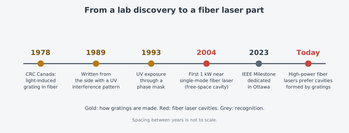
The road from discovery to product was not a single step. The literature notes that much additional work by many people came before FBGs became a commercial reality. In August 2023 an IEEE Milestone was dedicated at the CRC in Ottawa. Its citation says such gratings fit easily into fiber systems and "have revolutionized the design of optical communications and sensor systems.".
The two mirrors of a fiber laser
Fiber lasers did not use gratings as mirrors from the start. According to Coherent's webinar slides on fiber, the first 1 kW near single-mode fiber laser was shown in 2004. It came from the Optoelectronics Research Centre (ORC) at the University of Southampton in the UK and used a free-space laser cavity. That means mirrors and lenses placed in open air outside the fiber.
Higher power changed the picture. The same slides say free-space optics inside the cavity have turned out to be unreliable at the high powers today's fiber lasers reach. Monolithic designs that build the cavity out of fiber Bragg gratings are now preferred.
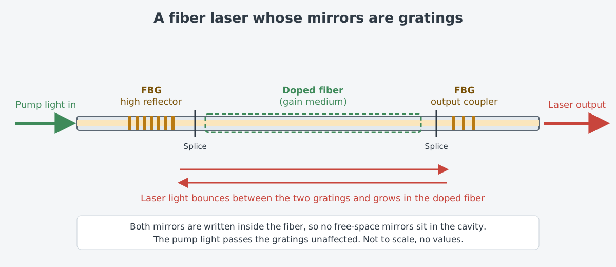
The layout is simple: at one end of the doped fiber, which is the gain medium, sits a high-reflector grating that sends almost all the light back. At the other end sits an output-coupler grating that lets part of the light out. The fiber pieces are joined by splices. Laser light grows as it travels between the two gratings and leaves through the output coupler.
As for the pump light, it passes along the fiber unaffected when the gratings are written into the core of a double-clad fiber. How pump light and laser light take separate paths is covered in Double-clad fibers and how pump light gets in. The whole fiber laser is described in What is a fiber laser? Growing light inside a thin glass fiber.
Manufacturers present this part as central to the cavity. On its product page, Exail describes FBG mirrors as a critical component for designing laser cavities and as well suited to high-power fiber lasers.
As power keeps rising, though, the grating also has to survive that light. A paper released as a preprint in 2014 named designing an FBG able to survive multi-kilowatt power as a technical challenge. That thread continues in Oscillators and amplifiers: making light, then growing it.
A wavelength that moves with heat and strain
The Bragg wavelength is set by the grating period and the refractive index. If either one changes, the returned wavelength changes too. When the temperature around a grating changes, its thermo-optic properties change and so does the reflected wavelength. When pressure acts on it, the grating's dimensions change and so do its optical properties.
For a laser mirror, this behavior is a burden to manage. Exail offers FBGs in athermal packages, which remove the effect of temperature, and in wavelength-adjustable packages. In radiation environments, radiation can also shift the Bragg wavelength, so gratings written on radiation-hardened fiber are offered as well.
For a sensor, the same behavior is the whole point. How far the reflected wavelength has moved tells back the temperature or pressure.
In 2012 the US National Institute of Standards and Technology (NIST) described work on using FBGs to sense temperature and pressure with high sensitivity. It also published a study of FBG thermal response from 233 K to 393 K (roughly minus 40 to 120 degrees Celsius). Sealed in dry argon, the FBGs showed a quadratic dependence on temperature.
The trade-offs are clear. A NIST researcher said their FBG is not as accurate as a ring-resonator thermometer. In his words, it is "lightweight, free of EM interference, essentially passive," and it "survives in harsh environments where current technology will not survive." Multiplexing signals, which is harder with electrical measurements, was named as another advantage.
NASA's Fiber Optic Sensing System (FOSS) puts multiplexing to work. FBG sensors sit in a fiber spaced as closely as 0.25 inches (about 6 mm), and the fiber is attached to or built into a structure. A DFB laser that has no moving parts reads the wavelength shifts caused by stress or pressure, and the system turns them into shape, position, temperature, liquid level and loads. NASA states that one instrumentation system weighs less than 10 pounds (about 4.5 kg).
What it gives and where it falls short
Here is what the grating offers. It is part of the fiber itself, so it integrates easily into fiber systems. It returns one wavelength very selectively, and in a laser it does away with free-space mirrors inside the cavity. As a sensor it is light, free of electromagnetic interference, and able to line up many measuring points along one strand.
The limits come from the same places.
- It is sensitive to its surroundings. Temperature, pressure and radiation move the Bragg wavelength. That helps a sensor, but a laser mirror that must hold its wavelength has to manage it. Because the grating period is close in size to the working wavelength, making the grating is also very sensitive to environmental conditions.
- Cladding modes appear. The index changes along a grating can excite cladding modes that travel backward. In a narrow grating they mostly show up as ripples or extra peaks in the transmitted light, at wavelengths a little shorter than the Bragg wavelength. They are unwanted in manufacturing and can be reduced or largely suppressed with special fibers.
- The material comes with conditions. Writing with ultraviolet light needs photosensitive fiber.
- High power is a strain. Designing gratings that withstand multi-kilowatt light has been named as a technical challenge.
- Accuracy has limits. As the NIST researcher put it, an FBG is not as accurate as a ring-resonator thermometer.
What to read next
- "Volume Bragg Gratings: Holding a Pump Diode's Wavelength in Place": the same Bragg reflection, written into a block of glass instead of a fiber, used to hold a pump diode's wavelength.
- What is a fiber laser? Growing light inside a thin glass fiber: the full picture of how light grows between two gratings.
- Following One Laser Weapon: From Chip to Effector: where small parts such as gratings fit in the chain of parts of a laser weapon.