A glass rod lies inside a coil with no current flowing. A filter sits at each end, and the far filter is turned 90° from the near one, so the light is blocked and the view goes dark. Then current flows through the coil, and the light that was blocked shows up again. A physics lecture demonstration at Harvard University shows exactly this scene.
The light comes back because the magnetic field from the coil turns the polarization of the light passing through the glass by a small amount. A Faraday rotator is a part built to use this effect on purpose. It sits at the heart of the optical isolator, which protects a laser from light coming back at it.
Even a single rotator raises plenty of questions. What sets the angle it turns, and why does the turn not undo itself when light goes there and back? The sections below follow those questions, then look at the parts built from that property and at what gets harder as power rises.
1845: a magnet twists light
Polarization describes a wave whose oscillation points in a fixed direction compared with the way the wave moves. For light, that direction is the one in which the electric field points. A polarizing filter passes only the electric field along its own axis. That is why two filters with their axes crossed at right angles block the light.
In 1845 Michael Faraday showed by experiment that a magnetic field can affect the polarization of light. While polarized light passed through heavy glass, he applied a magnetic field to the glass, and the plane of polarization turned slightly. The Harvard demonstration notes present this discovery as the first evidence that light and magnetism were somehow connected.
Materials that turn polarization this way inside a magnetic field are called magneto-optic materials. A Faraday rotator is an optical part in which such a crystal sits inside a magnetic field. Its one job is to turn the polarization direction of the light passing through it.
The opening demonstration has a second half. After the current is switched on, turning the far filter further makes the light go dark again, because the filter now follows the polarization by the angle it turned. Reverse the current in the coil, and the polarization turns the other way.
How far it turns
The turning angle is directly proportional to three things. They are how strong the magnetic field is, how far the light goes through the material, and the Verdet constant, which differs from material to material. Written as one line:
θ = V × l × B
Here θ is the angle the polarization turns and V is the Verdet constant. The letter l is the path length of the light within the material, and B is how strong the field is along that path. Doubling the field or doubling the crystal length doubles the angle.
The Verdet constant is a measure of how strong the magneto-optic effect is in a given material, and it is usually found by measurement. Most transparent dielectrics show the effect, but it is usually very weak. Only a few materials have a large Verdet constant, and these are typically glasses or crystals that contain terbium.
Among them, terbium gallium garnet (TGG) crystal is widely used. The manufacturer Coherent describes TGG as showing a large magneto-optic effect with low absorption at commonly used wavelengths. That makes it one of the most common materials for rotators and isolators.
The Verdet constant has one tricky feature. Its value changes with wavelength. In the Harvard demonstration, which uses light from an incandescent bulb, you can see this. No angle of the far filter puts out all the light, and different colors are selectively put out depending on the filter angle.
A turn that does not undo itself
The most important property of a Faraday rotator is something else. It turns polarization the same way every time, whichever side the light comes in from. If it is set to turn light passing one way by 45° clockwise, light entering from the other side also turns 45° in that same direction. After one trip out to a mirror and back, the total is 90°.
A half-wave plate also turns polarization, and it can be set to turn it by 45°. But light passing back through it is turned back by the same amount, so the net turn after a round trip is 0°.
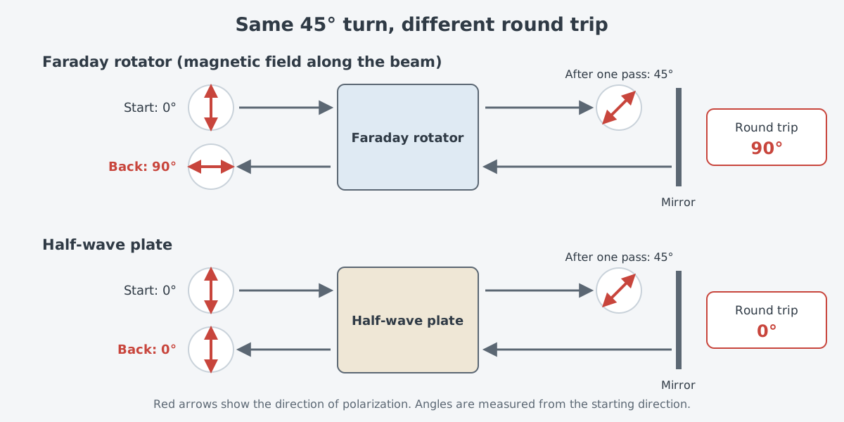
Think of a clock hand: a half-wave plate moves the hand forward on the way out and backward on the way in, so it ends where it started. A rotator moves it forward both ways. In reality nothing spins like a hand. What changes is the direction in which the electric field vibrates, and the sense of the turn is set by the magnetic field, not by the direction the light travels.
A property like this, where the result depends on the direction of travel, is called non-reciprocal. The isolators and Faraday mirrors below both rely on it.
There is one more difference from a half-wave plate. The rotator's angle is set by the applied magnetic field, so with an electromagnet instead of a permanent magnet the amount of turn can be controlled electrically. To change the angle of a half-wave plate, the plate itself has to be physically rotated, by hand or by a mechanism.
Building a one-way door from a rotator
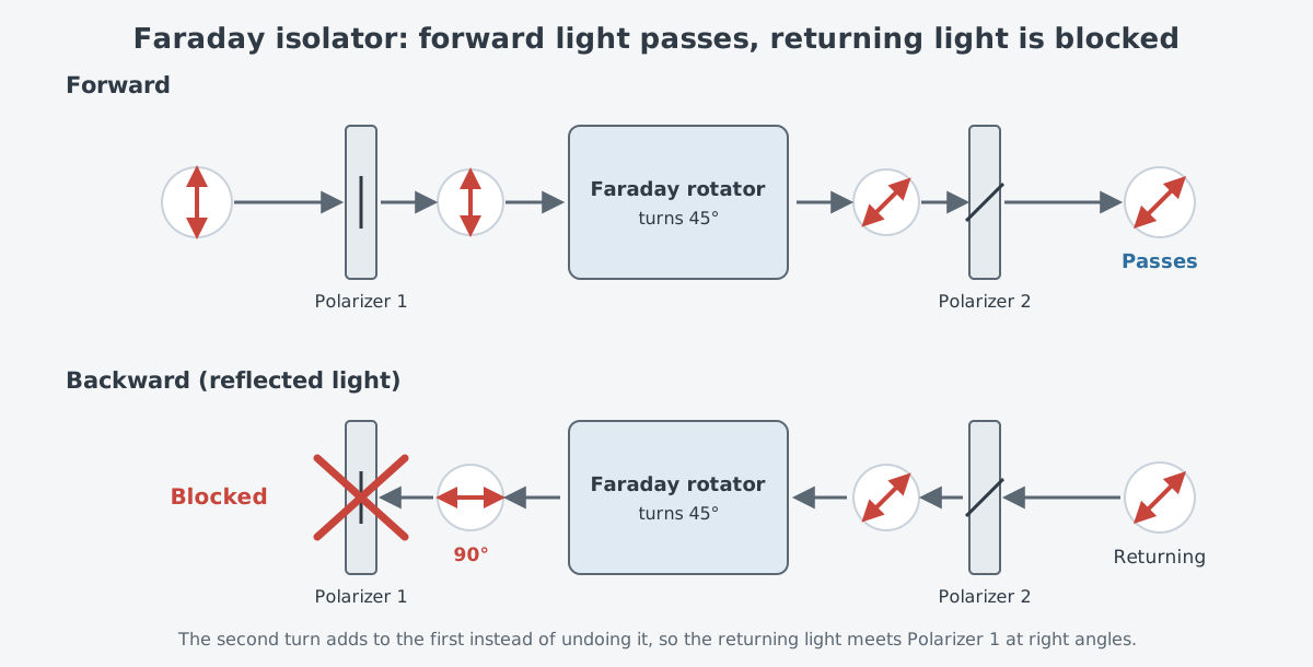
Add two polarizers to a rotator and you have an isolator. Linearly polarized light passes polarizer 1, which is lined up with its polarization. It turns 45° in the rotator and then passes polarizer 2, which is set to match the turned polarization. This arrangement lets forward-going laser light through with almost no loss.
Light going the other way takes a different path. Light reflected back from downstream first meets polarizer 2, which filters out any polarization different from the original output. What remains turns another 45° the same way in the rotator, ending at right angles to the original polarization. So it cannot pass polarizer 1.
Isolators are often placed where light leaves a laser or a laser amplifier. Light reflected back can harm the laser if it is strong enough, and even at much lower levels it can cause instability such as noise and power fluctuations. Where returning light comes from, and why it is harder to handle in fiber, is covered in Isolators and fiber components: keeping light from going backwards.
The same setup shows up often on the lab bench. Keller's textbook on ultrafast lasers describes an experiment in which a Faraday isolator blocks leftover reflections from a fiber end face from going back into the laser cavity. In another measurement setup, an isolator is built from two polarizing beam splitters and a Faraday rotator.
Rotators do more than guard a laser from the outside. In a ring laser, where light circulates around a loop-shaped cavity, an isolator placed inside the cavity can make the light travel in only one direction. If the gain medium is an ideal, homogeneously broadened one, such a one-way ring laser lases in only one axial mode.
In some lasers the laser crystal itself does the turning. In a monolithic ring laser called a nonplanar ring oscillator (NPRO), the cavity is formed inside the laser crystal. Applying a magnetic field to that crystal produces Faraday rotation inside the YAG, which forces the laser to run in one direction only.
Fiber light with no fixed polarization
An isolator built with two polarizers assumes light whose polarization is known. In ordinary single-mode fiber, however, stress or unevenness in the core creates random birefringence, which makes the polarization state of the light fluctuate along the fiber. In other words, it is hard to know in advance which way light leaving a fiber will be polarized.
Isolators that do not care about polarization were developed for this kind of light. A fiber isolator presented by Bell Labs in 1989 used a birefringent walkoff plate, a half-wave plate and a Faraday rotator to make transmission differ between the two directions. Its input and output fibers sat side by side at one end of the device.
The idea is to split the light and join it again, rather than block one polarization. In the forward direction, the two orthogonal polarizations separate on the first pass through the walkoff plate and come back together on the second pass. So transmission is high.
For light going the other way, the two polarizations separate on every pass through the walkoff plate. As a result the focus lands far from the input fiber, and the loss is high. The rotator works with the half-wave plate and the walkoff plate to create this difference between the two directions.
The Faraday mirror: a reflection that undoes the scrambling
Rotators are used for more than blocking light. A part that puts a rotator and a mirror at the end of a fiber is called a Faraday rotator mirror (FRM). According to an application note from a fiber component manufacturer, it consists of a fiber collimator, a Faraday rotator and a mirror.
Light turns 45° in the rotator, reflects off the mirror, and passes through the rotator once more. Because the turn is non-reciprocal, the polarization of the returning light ends up rotated 90° from the light that went in. However much the fiber scrambles the polarization along the way, the outgoing and returning light are always at right angles to each other, wherever you look along the fiber.
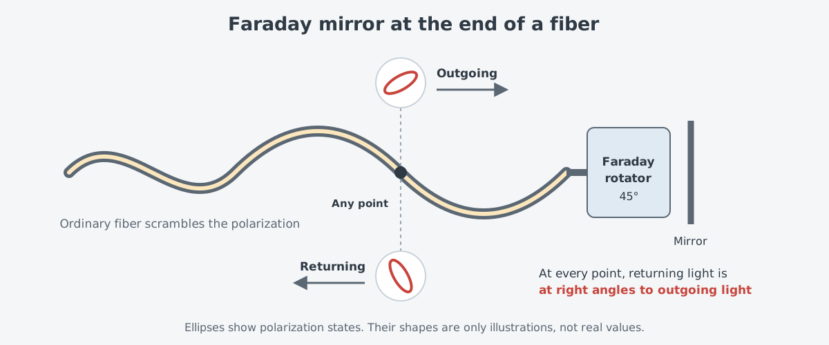
The same note states that the part cancels all linear birefringence effects over the round trip. Listed uses include fiber interferometers and fiber sensors, tunable fiber lasers, diffraction grating systems, and erbium-doped fiber amplifiers. In an amplifier, it lets the signal pass through the erbium-doped fiber twice to raise efficiency.
At high power the crystal heats up
As power rises, heat becomes the problem. Light absorbed in the crystal heats it locally, and that heat limits performance.
For years, TGG has been the usual rotator crystal for wavelengths from 650 to 1100 nm. As Coherent explains, though, even the purest TGG eventually runs into performance limits because of its bulk absorption. As industrial lasers grew more powerful decade after decade, the absorption and thermo-optic behavior of TGG turned into a growing drawback.
There are efforts to change the material. The same company states that potassium terbium fluoride (KTF) has a transmission range similar to TGG and a comparable Verdet constant. It adds that KTF absorbs eight times less in the bulk and that its thermo-optic coefficient is 15 times smaller. The company claims this lets it avoid the loss of isolation, beam focus and beam quality that TGG isolators suffer at very high laser power.
Why is heat such a problem? An isolator blocks returning light by turning its polarization to lie at right angles to the polarizer. A 2016 review paper counts the Faraday isolator among the key elements of high-power lasers. In that role, the isolator optically separates the master oscillator from the power amplifier (MOPA).
But heating of the magneto-optic medium by absorbed light cannot be avoided, and that heat distorts the polarization and phase of the beam. Even a very small polarization distortion makes the isolation ratio, the key measure of an isolator, worse. The review sees these thermal effects as limiting the use of isolators in lasers with high average power.
Gravitational-wave detectors are one place where this problem has been studied in detail. A 2012 journal paper wrote that Advanced LIGO and Advanced Virgo, two second-generation gravitational-wave interferometers, use continuous-wave lasers of up to 200 W. At that power, it said, they need specially designed isolators that are not thrown off by absorption-degraded isolation, thermal lensing, or heat-induced beam steering.
Earlier, at a 2007 American Physical Society meeting, a University of Florida team reported high-power tests, noting that the Advanced LIGO upgrade would need power of up to 180 W. The abstract states that two configurations tested at 100 W input gave isolation of 39 dB and 49 dB. Isolation in decibels (dB) means that a higher value blocks more of the returning light.
Choosing an isolator is not simple either. Coherent lists aperture size, wavelength range, transmission and isolation as the key parameters of an isolator. Meeting them, it explains, takes trade-offs among how strong and how large the magnet is, the quality of the crystal, and the thin-film coatings. Crystal quality here means absorption, uniformity of the refractive index, and birefringence.
For other heat problems that come with higher power, see Limits of a single fiber (2): heat and mode instability. The cooling side is covered in Cooling and thermal management: where the heat that did not become light goes.
What to read next
- Polarization: the direction in which light vibrates: the basics of polarization this article builds on, such as linear polarization, polarizers and wave plates.
- Isolators and fiber components: keeping light from going backwards: where returning light comes from and why it is more dangerous in fiber lasers.
- Oscillators and amplifiers: making light, then growing it: the oscillator and amplifier layout that an isolator sits between.
- "Polarization-Maintaining Fiber: Keeping Light's Orientation Fixed": a way to deal with drifting polarization from the fiber side.