A strand of optical fiber is about as thin as a hair. The path that carries light down its center is far thinner still. How do you join two such strands end to end so that the light passes the joint as if it were not there?
Fiber optic networks laid around the world face this question, and so does every fiber laser in a factory. This article looks at how fusion splicing, which melts the glass ends together, works, why it has to be so precise, and what part it plays inside a fiber laser.
Three ways to join fibers
Fiber joining falls into two broad groups. Permanent connections stay in place once made, while connectors can be plugged in and pulled out. Permanent connections split again into fusion splicing and mechanical splicing.
The International Telecommunication Union (ITU) Recommendation L.400/L.12 also names fusion and mechanical splicing as the two technologies for joining glass fibers, and says both are meant to be permanent. Which one to choose depends on the performance expected and on installation and maintenance needs.
Trunk lines that carry heavy traffic over long distances need fusion splicing. A connector is handy because it plugs in and out like an electrical plug. Fusion splicing instead turns the two strands into a single strand of glass.
Melting with a spark: how fusion works
A fusion splicer creates an arc discharge between two electrodes. An arc discharge is a kind of gas discharge: the two electrodes, and the gas in the gap, heat up strongly and glow brightly. It is the same effect used in welding.
The splicer melts the ends of the two fibers, set on its left and right, with the heat of this arc and joins them in an instant. Sumitomo Electric, a Japanese splicer maker, puts that heat at about 1,800 °C. Telecom fiber is made of silica glass, so once the melted ends cool, they form one strand of glass.
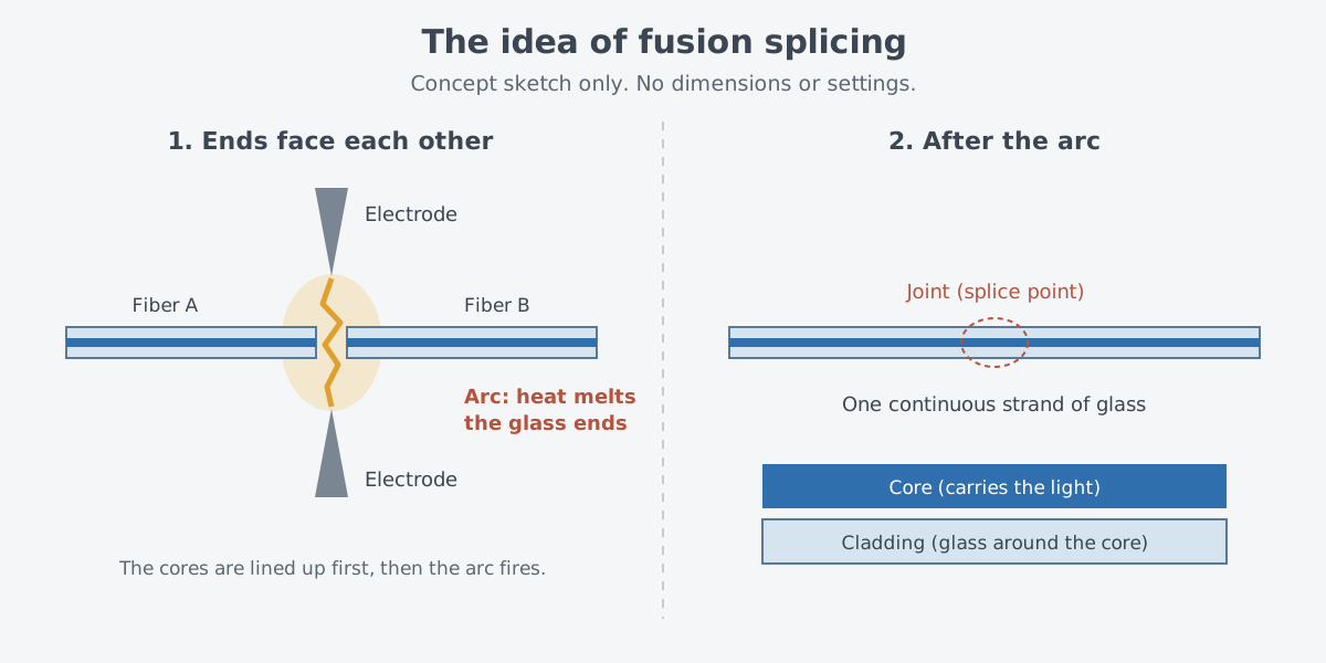
The work itself means stripping the coating to expose the glass, cutting the ends, joining them with the arc, and covering the joint with a protective sleeve to reinforce it. Of these steps, the cut has a real effect on splice loss, which makes the quality of the cut faces critically important.
Why the precision matters
Inside an optical fiber, a core sits at the center, and cladding wraps around it in a concentric layer. Light that enters the core moves forward by reflecting again and again at the boundary between core and cladding. What a fusion splice really has to join is the end of one core to the end of the other.
Fibers come in two types. Single-mode fiber (SMF) has a thin core, and multi-mode fiber (MMF) has a thick one. An SMF core is only 9.2 µm across, or 0.0092 mm, while an MMF core is 50 µm or 62 µm. SMF serves fast, long-distance links, and MMF is mostly used in cables inside buildings.
With cores this thin, lining up the two strands accurately is what decides the quality of the splice. If the fiber axes are offset sideways, tilted at an angle, or separated by a gap, each case causes splice loss. With a gap, some light reflects at the boundaries because glass and air have different refractive indices.
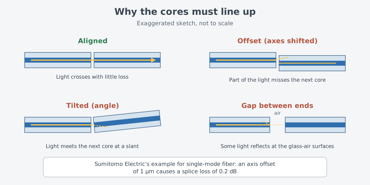
How sensitive is it? Sumitomo Electric gives an example for single-mode fiber: shift the axes by just 1 µm (0.001 mm), and the splice loses 0.2 decibels (dB). That is why the ends must be matched with submicron precision, finer than 1 µm.
Picture two people, each holding a needle, trying to touch the eyes of the needles together. In practice a machine moves the fibers, not a hand, and the target is not a needle's eye but a core hidden inside the glass. The question of how to align a core you cannot see from outside has reshaped splicers several times.
From aligning by eye to machines that see the core
Sumitomo Electric says it launched its first fusion splicer in 1980. It was built for multimode fiber, and the operator lined up the fibers by looking through a microscope at their outer edges. With the thick cores of multimode fiber, this could keep splice loss down, but how well it worked came down to the skill of the person at the microscope.
A single-mode core is about one-fifth as wide as a multimode core. To handle it, the splicer the same company released in 1982 aligned fibers by the amount of light. A light source sat at the far end of one fiber and a detector at the far end of the other. The cores were then moved to where the detector saw the most light.
This approach was a lot of trouble. The source and detector had to be placed at sites hundreds of meters to several kilometers apart, and each splice took a long time. The next step was to look at the core directly.
In 1984, Sumitomo Electric released a splicer with direct core monitoring, which views the fiber cores through a high-power microscope and aligns them automatically. A later model added a CCD camera to its imaging system so the machine could see the cores and align them by itself. Fujikura, for its part, says it pioneered the Profile Alignment System (PAS) for observing the fiber core in fusion splicers in 1985.
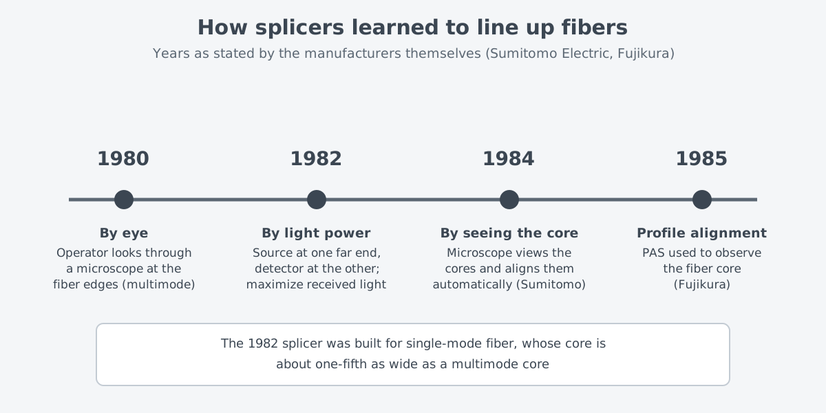
These years are as each company states them. In the 1980s and 1990s, Sumitomo Electric often developed splicers jointly with its competitors, with a telecom carrier taking part.
Splicers then grew smaller and lighter. Battery models for places without AC power, such as manholes and high sites, appeared in the late 1990s, and from 2000 on, small, light, battery-powered splicers became the norm.
There is more than one way to line up cores. To splice many fibers at once, splicers use stationary V-groove alignment, which lays the fibers in precisely machined V-shaped grooves. They also rely on surface tension in the melted glass, which tends to pull the cores into line on its own. Fusion splice alignment methods thus include active core alignment, active cladding alignment, and passive V-groove alignment.
What makes a good splice
ITU-T L.400/L.12 treats splices as critical points in a fiber network, since how well a link performs, and how long it lasts, depends heavily on them. A high-quality splice is usually judged on two counts: it loses little light, and it is nearly as strong in tension as the fiber's proof test level.
There is one more requirement. A splice should keep performing steadily for as long as the link is designed to last, in the conditions expected at its site. Being good on the day it is made is not enough; it has to hold up for years where it is installed.
Joining two different fibers is harder. Here, loss increases with differences in mode field diameter, core-cladding concentricity, and cladding diameter. In the late 2000s, fibers that bend more easily spread for indoor wiring, and they needed splicing conditions different from those of ordinary single-mode fiber. Choosing the wrong conditions caused defects such as higher splice loss, so splicers moved toward identifying the fiber type on their own from captured images.
Fusion splicing in fiber lasers
A fiber laser rests on this splicing technology. Fibers can differ in type, glass makeup, and core size and still be spliced together. That lets builders tie the pump sources, the part that amplifies light, and the delivery fiber into one system without free-space optics. IPG Photonics, a fiber laser maker, lists contamination, damage, and misalignment as the risks of free-space optics, meaning lenses and mirrors set up in open air.
A layout joined by splices from start to finish is called monolithic. A 2013 Coherent webinar deck sums up that monolithic designs built from spliced parts remove the need for realignment, which greatly helps reliability and cuts servicing. At the power levels of today's fiber lasers, lenses and mirrors inside the laser cavity turned out to be unreliable. Monolithic designs that form the cavity with fiber Bragg gratings (FBGs) are now preferred instead.
By 2013, when that deck was made, monolithic fiber lasers built by splicing ytterbium-doped large-mode-area fiber (LMA) to LMA Bragg gratings already ran routinely above 1 kW. LMA fiber, with its enlarged core, is a strand used in high-power fiber lasers.
As power rises, a splice can become a weak spot. Running an LMA fiber laser above 1 kW means the fibers in each stage of the amplifier must be carefully matched to one another. Splice loss between the active fiber that amplifies light and the passive fiber that only carries it can make splices fail at high power or degrade beam quality. This is why fiber makers now offer families of LMA fibers that are matched to each other for high power.
A splice is also a place where light leaks out. In multi-kilowatt lasers that use double-clad fiber (DCF), light straying in the cladding harms reliability and beam quality. An SPIE paper by OFS researchers traces it to three sources. They are pump light the core did not absorb, amplified spontaneous emission (ASE), and light that scatters where the fiber is spliced or bent.
Fiber laser makers also use splicers different from telecom models. Fujikura Europe says its specialty splicers can handle many kinds of specialty fiber, large-diameter fiber, and heat-sensitive fiber. For one such model, it lists polarization-maintaining fiber (PM) splicing and fiber laser manufacturers among the uses. The need for accurate, consistent splices has spread beyond telecom into manufacturing, research and development, and medicine.
What to read next
- How a fiber guides light: core and cladding: how the core you line up here actually holds on to light.
- Double-clad fibers and how pump light gets in: a fiber that gives pump light and laser light separate paths.
- Pump and Signal Combiners and Endcaps: Fiber Parts Inside an Amplifier: the parts inside an amplifier that splices tie together.
- "Cladding Light Strippers: Where Leftover Pump Light Goes": a part that removes cladding light, including light scattered at splices.