Split red laser light (630 nm) into two beams and lay them back over each other. Move one mirror by 315 nm, and the bright and dark fringes on the screen shift by exactly one place. The numbers come from an example in a university physics textbook, and 315 nm is half the wavelength of that light.
Turn this around and a problem appears. If the holder under that mirror shakes by the same tiny amount, the fringes shake too. That is why a laser lab floor carries a heavy plate dotted with threaded holes, and why each mirror and lens on it sits in its own small holder.
The plate is an optical table, and the holders are mounts. This article looks at why the table has a honeycomb inside, what the air in its legs does, and how a mount holds a part in place. At the end it goes back to an 1887 experiment that floated a stone slab on mercury.
Light notices nanometers
Interference is what happens when two beams of light overlap and add to or cancel each other. A Michelson interferometer is a precision instrument that splits light into two parts, sends them along different paths and then recombines them to make interference fringes. Move one mirror by half a wavelength and the path difference changes by one wavelength, so each fringe moves to the spot its neighbor held.
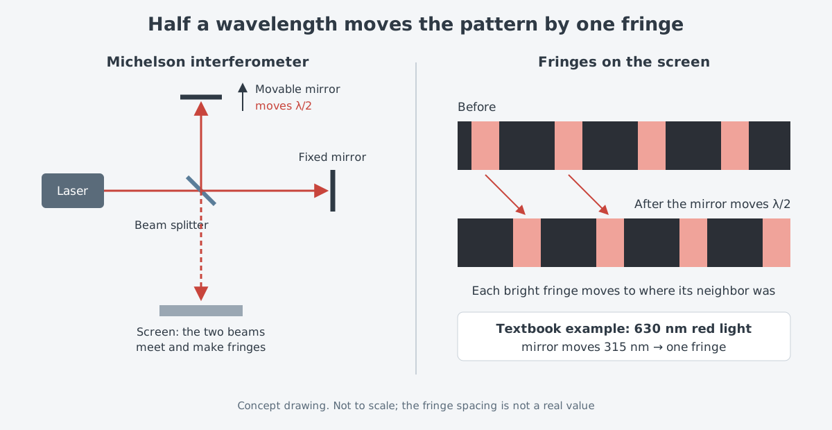
By counting the fringes that pass, you can measure tiny displacements down to a small part of one wavelength. That is why interferometers are used for precise measurement. The same property makes them just as sensitive to unwanted shaking.
The gravitational-wave observatory LIGO takes this sensitivity furthest. According to the LIGO Lab, gravitational waves change the distance between its mirrors by 10⁻¹⁹ m. Its interferometers can feel traffic on nearby roads, weather on the other side of the continent, ocean waves and nearly every large earthquake on the planet. So each 40 kg mirror hangs from a 360 kg four-stage pendulum, and the whole is wrapped in several layers of active and passive vibration isolation.
An optical table in an ordinary lab works toward the same goal. It keeps the parts along the beam from moving relative to one another.
Nothing is perfectly rigid
In a perfectly rigid body, no two points ever move closer together or farther apart. If every part were tied into one such body, no part would move relative to another, and the optical system would not lose performance. Since sources of vibration can never be removed completely, the goal is to link the parts with a rigid structure and cut their relative motion.
The trouble is that no structure is perfectly rigid. A Newport technical note sorts the forces to deal with into three groups instead.
| Force | What it does | How to reduce it |
|---|---|---|
| Dynamic forces (vibration) | The structure deforms in step with the driving frequency, and structural resonance can amplify relative motion between optical parts | Link parts in a rigid structure with damped resonances, and block floor vibration with mechanical filters or active cancellation |
| Static forces | Deformation that does not change with time. Adding or moving equipment changes it and throws parts out of alignment | A stiff structure that bends very little when pushed from outside |
| Temperature | Uneven temperature changes usually bend the structure slowly, over an hour or more | Reduce temperature changes, and design the structure to be insensitive to temperature |
Shaking usually brings vibration to mind. Yet, as the third row shows, a slow bend that takes more than an hour can also spoil the alignment.
A table with a honeycomb inside
An optical table is the rigid base for precise optical experiments. It is built so that parts along the beam do not shift against each other and cause errors, and rigidity is the first thing its design weighs. Rigidity has two sides. Static rigidity means bending little when equipment is moved or added, and dynamic rigidity means bending little when floor vibration, sound or machines on the table shake it.
Most optical tables are built as a sandwich: two face plates with a light honeycomb core between them. Honeycomb is a common shape for structures that are very light yet very stiff. A lighter structure moves its bending resonances to higher frequencies and bends less under the same vibration force.
Newport's catalog names this as the main reason for the shift from granite to steel honeycomb in most demanding optical work. Granite is heavy, so its resonances sit at lower frequencies and its surface bends more.
Honeycomb also brings high damping. Disturbances from relative motion between parts usually come from the table's main bending or twisting modes, and damping shrinks those vibrations and cuts relative motion across the surface. In very precise work such as optical interferometry, getting the most damping is critical.
Even the threaded holes on top get careful treatment. On this company's tables, the mounting holes sit on a 25 mm (1 inch) grid, and each hole is sealed underneath by a non-corrosive cone-shaped cup. The cups keep laser dyes, cooling fluids and the odd spilled coffee from seeping into the honeycomb.
Air springs in the legs
A table usually rests on soft pneumatic vibration isolators. Inside each isolator is a chamber of compressed air sealed by a flexible diaphragm, and this air holds up the table through a piston. When the piston is pushed into the chamber, the air pressure rises and pushes back like a soft spring.
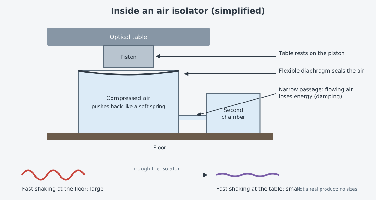
Any system of a mass on a spring has its own natural frequency. Like a tuning fork for the note A that rings at 440 Hz, it is the frequency at which the system vibrates on its own once disturbed. In a mass-spring system, the natural frequency drops as the mass grows or the spring gets softer. In an air isolator, a bigger air chamber gives a lower natural frequency.
How much floor shaking reaches the table falls into three ranges by frequency. Shaking much slower than the natural frequency passes straight through, shaking near the natural frequency is actually amplified, and shaking much faster is filtered out.
An air isolator is a kind of mechanical low-pass filter. Lowering the natural frequency lets it filter slower shaking too, so lowering it is the main design goal. For a graph of the three ranges, see the transmissibility figure in Vibration and shock: protecting optics on a moving platform.
Damping is what lowers the peak. Just as a tuning fork stops almost at once when its tips are dipped in water, damping drains energy from the motion so the vibration dies out sooner. In an air isolator, air loses energy as it flows through a thin tube or small hole into another chamber, and this acts as the damping.
It is not free. More damping lowers the resonance peak, but the fall-off for fast shaking becomes gentler. The designer has to trade natural frequency against damping.
Holding with six points: the kinematic idea
If the table is the floor, the mount is the hand. In any optical system, each optical part must be mounted somehow, and performance depends on the mounts and positioning accuracy as much as on the optics.
A three-legged stool shows the idea behind a mount. Even if its legs differ a little in length, all three always touch the ground. There is a cost in practice: the load must stay within the triangle of the legs, so the stool tips over more easily.
Exact constraint design puts this idea into a rule. The number of points that hold a part should match how many degrees of freedom need holding. A kinematic coupling holds exactly six degrees of freedom: its six contact points fix where one part sits, and which way it faces, relative to another. Because contacts and degrees of freedom match one for one, its performance can be predicted.
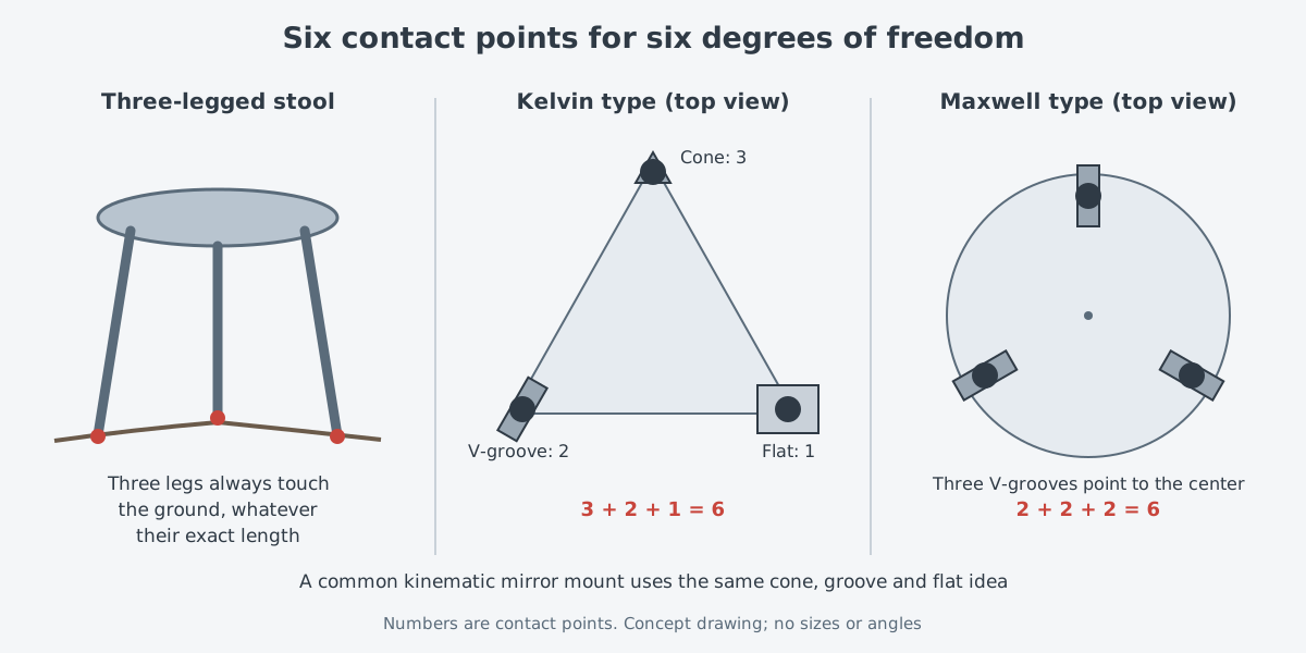
In the first of two named versions, a ball rests in a tetrahedral socket, a second in a V-groove pointing toward it, and a third on a flat. It is called a Kelvin coupling, named for Lord Kelvin, who liked this layout. The symmetric version, with three V-grooves pointing to the center and one ball in each, is the one James Clerk Maxwell preferred. A review by Alexander Slocum, professor of mechanical engineering at MIT, says both designs appear to date from the early 1800s, but the "inventor" is not clearly known.
Three ways to mount a mirror
Optical mounts that adjust a mirror's tilt up-down and left-right come in three basic designs. The most common kinematic mount uses the cone, groove and flat directly. At one corner of two spring-linked plates, a ball sits in a cone and acts as the pivot. One round-tipped adjustment screw pushes on a groove, and the other pushes on a flat, so each degree of freedom is held in only one way.
| Type | What it looks like | Features |
|---|---|---|
| Kinematic (cone, groove, flat) | Two spring-linked plates, a ball and adjustment screws | Good adjustment range and stability, and inexpensive. Not fully orthogonal, so changing the angle shifts the beam slightly sideways and the axes interact |
| Flexure | Plates linked by stiff leaf springs | Compact, with excellent mechanical and thermal stability. Less adjustment range than a kinematic mount |
| Gimbal | Two pairs of bearings set at right angles | Truly orthogonal motion. The center of rotation is at the mirror's front surface, so changing the angle does not shift the beam sideways. Often used for very large parts |
Mounts are judged on adjustment range, resolution, repeatability, orthogonality, stability, thermal drift and cost. Repeatability is how closely a mount comes back to the same spot for the same adjustment, and orthogonality is whether adjusting one axis leaves the other alone. Stability is how well the mount holds its position over time.
Resolution matters because of how mirrors behave. When a mirror turns by some angle, the reflected light turns by twice that angle. So placing light precisely far from the mirror needs a mount that can adjust to a smaller angle.
From a stone slab on mercury to today's tables
In July 1887, Albert Michelson of the Case School of Applied Science and Edward Morley of Western Reserve University ran an interferometer experiment. They worked below ground, in a dormitory basement at Western Reserve University in the United States. It was designed to detect Earth's motion through the aether, which was then thought to carry light. They made their observations in several concentrated periods between April and July that year.
Outside vibration had troubled their earlier work. Morley solved this with a mounting he designed: the interferometer sat on a large sandstone slab, and the slab floated and turned in a pool of mercury. The slab served as the table and the mercury as the support.
Even with these improvements, the experiment found no motion of the expected size. This surprising result puzzled physicists around the world until Einstein's theory of relativity appeared in 1905.
Company material carries the story to today's honeycomb tables. Newport describes itself as having pioneered the honeycomb optical bench, and says that in 2005 it was the first to sell optical tables with active damping. Active damping measures the shaking as it happens and uses actuators to cancel it. Both are the company's own account.
Outside the lab
Thermal drift is how far a mount's position shifts when the temperature changes, and mount design and materials affect it. In a temperature-controlled lab it is usually not a concern. In portable or airborne equipment, however, it can be critical, and it also has to be considered when mounting optics inside a laser that runs hot.
Tables and air springs are a good answer on a lab floor. "Vibration and shock" follows how optics on moving vehicles, ships and aircraft cope with shaking. Outside conditions such as rain, dust, heat and cold continue in Environmental durability: rain, dust, heat, cold and salt. For fixing the small shake that tables and mounts cannot stop by using a quick mirror, see Fast steering mirrors: small, quick mirrors that cancel shake.
What to read next
- Inside a laser lab: from the optical table to the power meter: the other equipment that sits on the table, in one layout drawing.
- Interference and diffraction: how light adds up and spreads: why interference fringes appear, from the start.
- Coherent beam combining: the principle, from published reviews: how interference is used to merge many beams into one.