Follow a spectral beam combining (SBC) system from front to back, and the light that left many separate amplifiers finally meets on one plate. The output of every channel crosses that plate at once. That plate is a diffraction grating.
What spectral beam combining is was covered in Spectral Beam Combining in Detail. This article looks at one part instead of a method. How does a grating bend light, and what does it have to endure under strong light?
How a striped plate splits colors
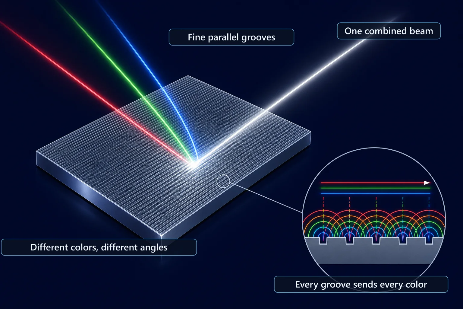
A diffraction grating is a plate with fine lines, the grating lines, packed closely at an even spacing. In a reflection grating, each line that light reaches sends out a small wave of its own. These waves spread in all directions, and as they overlap they grow strong in some directions and vanish in others.
Which directions grow strong? When waves from two neighboring lines head in some direction, the paths they travel differ slightly in length. If that difference is exactly one wavelength, crest meets crest again and the waves reinforce each other through interference. Each additional line shifts by exactly one more wavelength, so the waves from every line build up together in that direction.
A direction where the waves build up like this is called a diffraction order. The direction with zero path difference is the zeroth order. It is the plain mirror-like reflection, so it does not separate colors. The direction with a one-wavelength difference is the first order, and two wavelengths give the second order.
Colors part from the first order on. A longer wavelength needs a steeper tilt to build up a one-wavelength path difference, so the first order of red light bends more than the first order of blue light. This change of angle with wavelength is called dispersion, and since it shows up as an angle it is also called angular dispersion. A grating that spreads the same wavelength difference over a wider angle has more dispersion.
Picture a choir standing in a row. Everyone sings the same note, but a listener standing off to the side hears each voice arrive slightly later than the one before. Where the delay equals exactly the time the sound takes to vibrate once, the voices line up again and get louder. The lower the note, the longer one vibration takes, and the farther to the side that direction lies.
The real case differs in some ways. Light has a far shorter wavelength than sound, and a grating does not sing by itself like a choir; it only sends back the light that reaches it.
Spectral combining uses this property in reverse. Send each color in from the right direction, and the light bent into the first order leaves overlapped in one direction. The Interference and Diffraction article covers the principle in more detail.
Its place in spectral combining
There are two broad ways to merge beams of different wavelengths. The serial approach places one combiner per wavelength and adds beams one after another. It needs as many optical elements as there are wavelengths, and it has also been built with volume Bragg gratings that have a narrow spectral width.
The parallel approach merges many wavelengths at once with a single diffraction grating. The more wavelengths you add, the more the parallel approach pays off, because adding a color needs no new part, only one more beam on the same grating. The grating people usually mean in spectral combining is this single plate.
So much of the design starts from the grating. A grating with more dispersion can sort out more beams within the same wavelength range, and the choice of grating sets that dispersion. A 2014 article in the journal of MIT Lincoln Laboratory also names this dispersive element as the critical one among the optical elements.
What a grating must do: efficiency and endurance
The job comes down to two things. Send the light into the wanted order with as little loss as possible, and take strong light without spoiling the shape of the bent beam.
Why does the first one matter so much? Light that hits a grating does not go into one order only. Spectral combining uses only the first order, so light leaking into the zeroth or other orders simply drops out of the combined beam. Most of the combining loss comes from light the grating sends into orders nobody wants.
That is why designers pick a grating that allows only the first and zeroth orders and work to shrink the leftover zeroth order. For one chosen polarization near the center wavelength, a grating can send very little light into the zeroth order. Polarization enters the condition because a grating responds differently depending on the direction in which light vibrates. A layout that sends the light back toward where it came from can also push first-order efficiency to its highest.
Real values exist too. According to the 2014 Lincoln Laboratory article, dielectric gratings have been made with 96% diffraction efficiency. Their absorption loss is below 10⁻⁴, so they can take strong light with almost no thermo-optical distortion.
Thermo-optical distortion happens when a surface absorbs a little light and warms up. The surface swells and its refractive index shifts, so a beam that passes through it or reflects from it gets distorted. The longer a grating takes strong light, the larger this problem becomes.
Dielectric instead of metal: the coating sets the heat
What covers the surface of a grating? A metal-coated grating is efficient thanks to the high conductivity of the metal. But where there is conductivity, absorption of light comes with it.
A 1995 conference abstract from researchers at Lawrence Livermore National Laboratory (LLNL) described a way around this absorption. The idea is to build high-efficiency reflection gratings from transparent dielectric materials only. Many thin dielectric layers stacked on top of each other provide the reflection, and grooves cut on top provide the diffraction. Building reflection out of stacked layers is the same idea as the Bragg mirror in the Mirrors, Lenses and Coatings article.
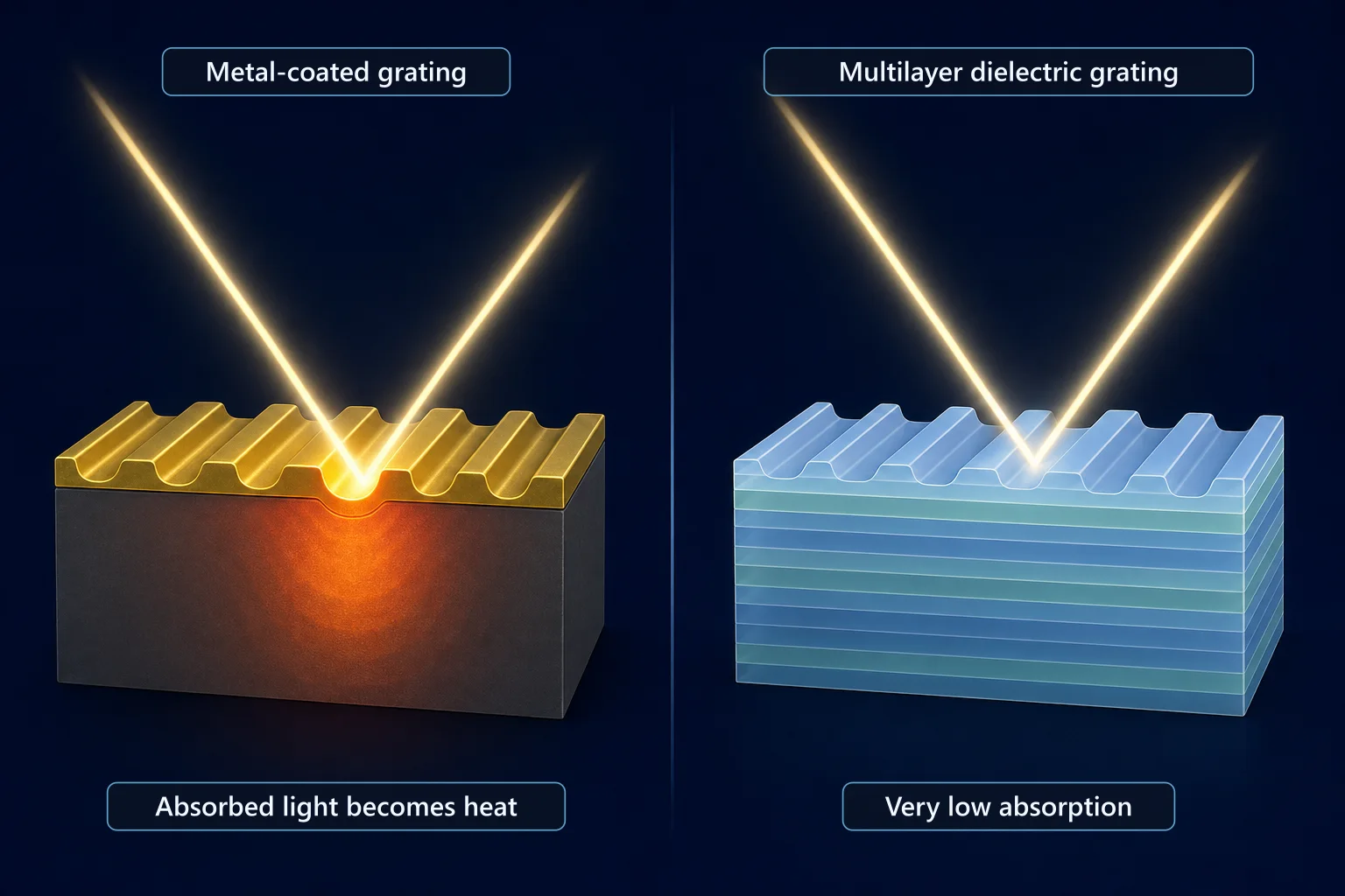
In spectral combining, this difference shows up as heat. Using dielectric layers as the optical coating instead of metal keeps absorption very low and raises combining efficiency. Less absorption also means a very low heat load on the grating, which greatly reduces the thermo-optical distortion described above. The Lincoln Laboratory article names this as a major benefit of dielectric gratings.
Strong light and heat: why the beam on the grating grows
The more beams are combined, the harder the grating's job becomes. Fitting in more beams means the beam on the grating has to grow, for two reasons. One is that the grating must resolve more beams from each other, which takes more resolution.
The other is heat and damage. The intensity of the light has to stay below a certain limit to avoid optical damage and thermo-optical deformation that would degrade the combined beam. Spreading the same power over a wider area lowers the intensity at each point of the surface. That is why the beam on the grating gets larger.
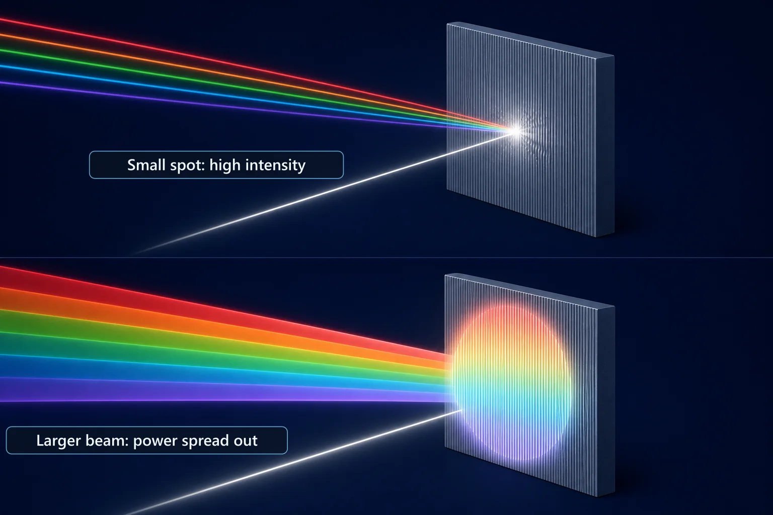
A larger beam has its own cost. When many high-power beams are combined, as with fiber lasers, the intensity limit makes the focal length of the optics that gather the beams very long. Covering that length with one lens or one mirror would leave a device far too big to use. Splitting the job over several optical elements, each kept below the intensity limit, lets the optics stay compact.
Linewidth and the grating
The grating is demanding about the light of even one channel. The light in each channel is not a perfect single color but has a small width called the linewidth. The grating bends the wavelengths inside that width at slightly different angles. The more dispersion a grating has, the wider the same linewidth spreads.
If that spread grows too large, the beam can no longer stay diffraction limited. A diffraction-limited beam spreads only as much as physics allows, which is the best possible beam quality. How narrow the linewidth has to stay, and why it is broadened a little on purpose, is covered in Spectral Beam Combining in Detail.
Damage seen in large gratings for pulsed lasers
Spectral combining is not the only place where gratings face strong light. In ultrafast lasers, the simplest layout with two gratings is normally used as a pulse compressor. In chirped pulse amplification (CPA), which stretches a pulse, amplifies it and then compresses it again, the compressor gratings take very intense pulses.
The 1995 LLNL abstract looked at high-efficiency gratings used as the dispersive element, as in a petawatt laser. It held that their weakness against laser damage caps the peak intensity that can be reached. According to a 2010 abstract, multilayer dielectric gratings built for petawatt-class lasers show unusual damage behavior. How finely each groove is shaped, and what absorbing impurities remain on the surface, both strongly affect the damage threshold (LIDT).
Gratings are also made large. A 2005 LLNL paper in the SPIE conference proceedings reported delivering the first multilayer dielectric grating with an 80 cm aperture to LLNL's Titan short-pulse laser facility.
These cases deal with very short pulses. In a spectral combining grating that takes continuous light for long periods, heat from absorption comes to the front, and damage may happen in a different way. Still, both uses reach the same conclusion. The surface and coating of a grating can set the upper limit of light that the whole laser delivers.
Gratings seen through conferences
The laboratory article and the LLNL abstracts above stop around 2014. Where gratings went after that can be followed through abstracts from Photonics West, the conference of SPIE, the international society for optics and photonics. The table keeps only talks that touch combining and damage.
| Year | What the public talks reported |
|---|---|
| 2023 | A talk that modeled the dispersion problem when broad-linewidth, high-power beams are spectrally combined with transmitting volume Bragg gratings, and proposed a way to compensate. A talk on the first chirped volume Bragg gratings written inside glass with ultrashort pulses, aimed at high-power chirped pulse amplification |
| 2024 | A talk that spectrally combined kW-class thulium fiber amplifiers with a double diffraction grating and reached 1.91 kW in the 2 µm band. The combining efficiency was 90%, and the temperature rise of the grating was also measured. Pump diodes with a grating built into the chip, which lock the wavelength without an outside grating, also appeared |
| 2026 | A kW-class high-brightness blue diode laser built with actively controlled dense wavelength beam combining |
| 2027 | A simple oscillator-amplifier design for a spectrally combined directed energy source, with the spectrum of each channel matched to the diffraction grating. A talk analyzing how damage starts and grows on a transmission grating in a large laser for fusion research |
Three threads can be read here.
First, spectral combining with gratings has spread beyond ytterbium fiber, to 2 µm thulium fiber and to blue diodes. Second, as in the 2027 talk, the idea of designing the source around the grating has appeared. Third, gratings now serve not only as combining parts but also as parts that hold the wavelength of pump diodes, and damage research on large gratings continues. The 2027 row comes from abstracts in the conference program, so details may change after the talks.
Same "grating," different jobs
The word grating comes up many times in laser articles. A fiber Bragg grating (FBG) is written inside the core of a fiber, and instead of fanning light out by direction, it sends one set wavelength back. The Isolators and Fiber Components article shows what it does.
Volume Bragg gratings have also served as combiners in the serial approach described above. The gratings in a pulse compressor spread colors to manage the length of a pulse. The name is the same, but the grating in spectral combining has the job of gathering many colors into one direction.
What to read next
- Spectral Beam Combining in Detail: follows how channels are divided and linewidths are managed before this grating.
- Mirrors, Lenses and Coatings: looks at multilayer coatings and how damage thresholds are measured, in mirrors and lenses.
- Incoherent Beam Combining: Side by Side, No Rhythm or Color to Match: compares a way to overlap beams with no grating at all.