How much power can one fiber laser deliver? Exail, a maker of these parts, says on its technical page that one unit reaches about a kilowatt, at most around 10 kW. It also says that phasing many of them can push the total into the hundreds of kilowatts.
One way to combine them is coherent beam combining (CBC). Why light with matched phase gathers into one beam was the topic of the earlier article Coherent beam combining: the principle, which explained it with interference. This article steps inside the system and follows the light, stop by stop, from the seed laser to the single beam that leaves.
The guide is the CBC technical page Exail has published, and this article follows its five parts in the order the page introduces them.
The whole route on one map
Start with the whole map. Light leaves a single seed laser and is split into many channels. Each channel passes a phase modulator and an amplifier, then a correction that undoes drift and a path length match. At the end all channels overlap into one beam again.
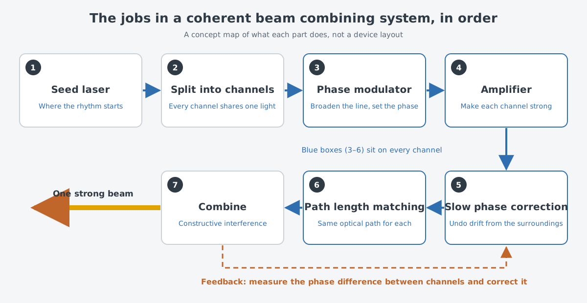
The map lists what the parts do, in order. It is not always where each part sits in a real device. For example, Exail presents a seed unit that holds an array of phase modulators, with optical delay lines as an option, in one box. So the parts that correct the phase may sit ahead of the amplifiers.
Think of a rowing boat. Even with many rowers, the boat moves well only when everyone pulls to one rhythm, and rowers out of rhythm cancel part of each other's effort. In the real system nobody listens for a beat. The rhythm of light is a physical quantity called phase, and the system measures and corrects it without a break.
First stop: one seed laser
The light in every channel comes from a single seed laser. This seed needs a narrow linewidth and low phase noise. You can think of linewidth as how wide a range of color the laser light holds.
Why start from just one? Feeding every amplifier from one shared seed is what gives the amplified beams the basis to interfere with each other. Channels that share the same light share the same rhythm from the start. The earlier article covers the conditions for interference in detail.
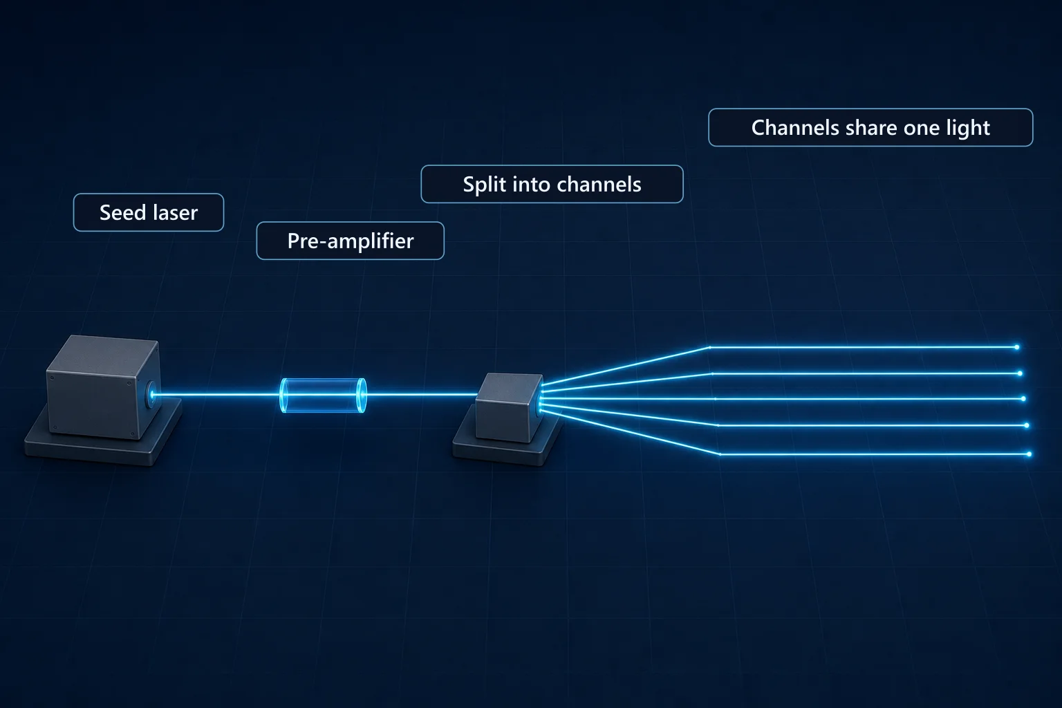
Before it is split and sent to the phase modulators, the seed light is amplified a few times.
Second stop: a phase modulator on every channel
Each channel has its own phase modulator. It is a fast, large-bandwidth phase modulator, and it has two jobs. One is to set the phase of each beam on its own. The other is to broaden the spectrum of the light on purpose.
The light started with a narrow line, so why broaden it again? The obstacle is stimulated Brillouin scattering (SBS). The maximum power each fiber amplifier can deliver is severely limited by this nonlinear effect. Broadening the linewidth with a phase modulator eases it.
What SBS is appears in detail in Limits of a single fiber (1): nonlinear effects (SBS, SRS). The point to keep here is the trade-off. The line is broadened by shaking the phase of the seed on purpose so that its frequency spreads a little. A review chapter on single-frequency amplifiers judges that this works well against SBS and, for some uses, leaves enough coherence to be useful.
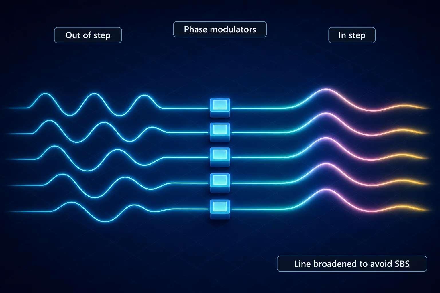
The broadening has a cost. That cost comes back at the fifth stop as the job of path length matching.
Third stop: growing the light in amplifiers
Now each channel's light is made much stronger. The core of an amplifier is a fiber that holds rare-earth elements. Exail lists large mode area fibers (LMA) doped with ytterbium (Yb), thulium (Tm) and holmium (Ho) for power amplifiers, for booster stages and kW-class amplifiers.
The element depends on the wavelength band. The 1 µm band uses Yb-doped fiber, and the 2 µm band uses Tm- and Ho-doped fiber.
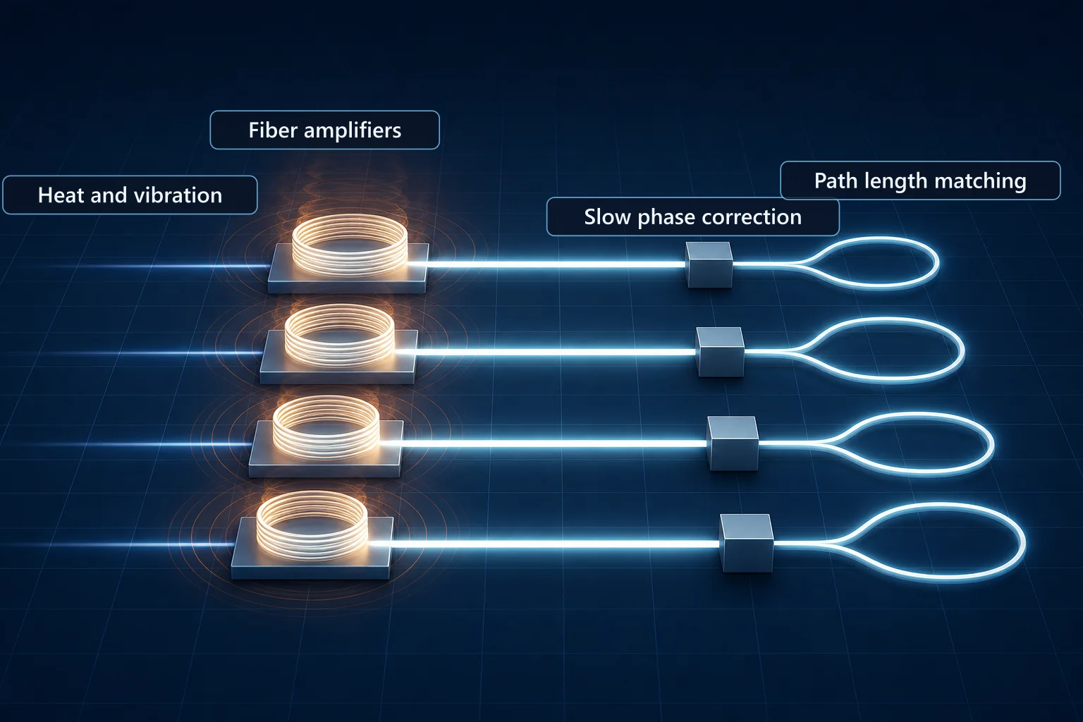
How an amplifier grows light is covered in Oscillators and amplifiers: making light, then growing it. This article looks at the problem that comes next. While light runs through a long fiber in each channel, the surroundings change the fiber length a little.
Fourth stop: slow correction that undoes drift
The part added here is, as its name says, a slow low-frequency phase modulator. It is separate from the one at the second stop, with one on each channel. It corrects the differences in fiber length between channels that come from disturbances in the surroundings. When the fiber length changes, the rhythm of the light at the fiber end changes too.
What causes the drift? The main causes are heat and sound or vibration in the surroundings. These were measured in laboratories, so the size can differ widely from place to place and with conditions.
A part that corrects drift is useless if it drifts itself. So this modulator has to keep its behavior when the temperature changes, and it must not create nonlinear effects that distort the light.
How does the system know how much to correct? It keeps measuring the phase differences between channels and runs a loop that turns each phase back by that amount. Most coherent combining systems include this kind of active phase stabilization, and each combiner design has several ways to build the loop. Thanks to it, the beams keep adding their strength together while they are combined.
It is like the lane-keeping feature in a car. When the car drifts a little, the steering turns a little to bring it back, and when the phase slips a little, the modulator brings it back by that much. In reality the thing being corrected is not a visible position but the phase of light, so even measuring it is the system's job.
Fifth stop: matching the path length
The last part is a variable optical delay line (VODL). Built from small optical assemblies, it makes the optical path the same for every beam.
Why match lengths when the phase is already corrected? The trade-off from the second stop comes back here. The laser linewidth sets the coherence length, and the coherence length sets the distance over which several beams can interfere with each other. A broader linewidth means a shorter coherence length.
You can think of the coherence length as the distance over which the rhythm of the light stays even. If two channels differ in path length by more than this distance, the two beams no longer overlap evenly, even when a phase modulator tries to set their rhythm.
If the coherence length is short, even small differences in path length matter, so the paths must be matched closely. The linewidth broadened to avoid SBS leaves path matching as homework. That is why slow phase correction and path matching work as a pair.
Last stop: overlapping into one beam
Beams with matched phase and length finally meet. How they gather into one beam was explained with interference in the earlier article. What matters here is that, whatever shape the combiner takes, the beams add their strength only when their phases match.
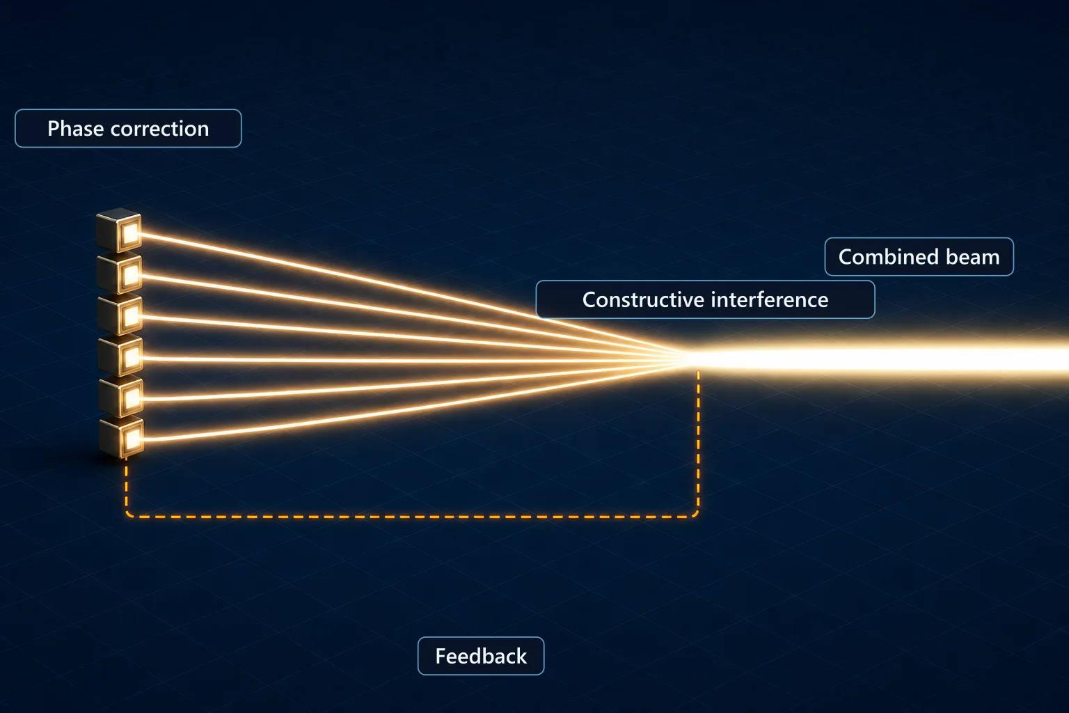
Which elements overlap the beams, and where light leaks when the phases slip, appeared in the earlier article with beam splitters and diffractive optical elements. The dashed feedback line on the map is the loop that measures that slip and sends it back to the fourth stop.
The parts in one box
The parts that have to sit on every channel are also available gathered into one multichannel rack unit. Every channel in the rack gets its own phase adjustment.
Phase modulators are not only for coherent combining. They also show up in spectral beam combining (SBC). A table comparing the two is in Why beam combining is needed, and its three approaches.
High-power fiber lasers now serve factory machines, lidar and large research laser facilities, and more recently they have spread into defense.
What makes it hard
More channels mean more parts. Phase modulators, amplifiers, correcting modulators and delay lines all have to sit on every channel. The combiner has the same issue. As a 2018 review notes, chaining elements that merge two beams at a time makes the part count climb almost in step with the number of beams.
The linewidth trade-off does not go away. Broadening eases SBS, but it shortens the coherence length, and the paths then need to be matched more precisely.
The size of the drift is not a fixed value either. Because heat and acoustics are the main causes, it can vary widely with the environment around the system. In that environment, the correcting parts must themselves stay unaffected by temperature and must not create nonlinear effects.
Power figures also call for care. The output values in this article are the ones the maker gives on its technical page. Another page from the same maker says that combining several fiber sources of a few kilowatts each can give tens to hundreds of kilowatts, which is worded a little differently.
What to read next
- "Coherent beam combining: the principle, from published reviews": why the beams gather into one at the last stop, explained with interference.
- "Limits of a single fiber (1): nonlinear effects (SBS, SRS)": a closer look at SBS, the reason the line is broadened at the second stop.
- "Why beam combining is needed, and its three approaches": coherent combining side by side with spectral and incoherent combining.