A laser mirror can take only so much light. The number that marks that limit is the laser-induced damage threshold, or LIDT. Trusting that one number on its own is risky, though. The same part can give a very different number depending on what light was used and how the test was run.
Mirrors, lenses and coatings covered what a coating is and how a damage threshold test works. This article takes the next questions. Why does damage happen, what changes with pulse length, and why does one speck of dust matter?
Later sections look at how a large U.S. laser facility manages damage. They also trace the meetings that have studied the problem since the 1970s, and the link to laser weapons.
What coatings do: dielectric and metal
An optical coating is material deposited in one or more layers on an optical substrate, designed to change how the part reflects or transmits light. The Bragg mirror and the anti-reflection coating (AR) from the earlier article are typical examples. A standard high-reflectance laser mirror is a stack of quarter-wave layers that alternate between high and low refractive index, and the textbook also calls it a dielectric Bragg mirror.
What are these layers made of, and how are they laid down? The materials table in Keller's textbook Ultrafast Lasers lists amorphous silicon dioxide (SiO₂) and titanium dioxide (TiO₂) deposited by ion beam sputtering. The properties of these layers depend on the deposition conditions.
Laying down the layers precisely is not easy. For double-chirped mirrors, which shape dispersion finely, the main challenge is very accurate control of the multilayer deposition. Keller writes that layer errors during fabrication are normally too large. A more accurate and affordable deposition method, the book adds, would help the ultrafast laser field a great deal.
Metal surfaces are another route, and researchers at Lawrence Livermore National Laboratory (LLNL) looked at them in a 1995 conference paper. They explained that metal gratings get their high efficiency from the metal's high conductivity, but conductivity brings unavoidable absorption of light. To avoid that absorption, they designed reflection gratings made only of transparent dielectric materials. The design merges a diffraction grating with the reflecting power of a stack of dielectric layers.
The background of that paper is worth noting. The LLNL Petawatt laser uses chirped pulse amplification (CPA) to make intense ultrashort pulses. In lasers like it, the gratings' weakness to laser damage limited the peak intensity that could be reached.
The substrate under the coating is chosen with care as well. Fused silica appears in manufacturer material as a good fit for high-energy lasers, because it can take high energy before damage.
What a damage threshold is
First, what counts as "damaged"? A 1997 NASA report defines optical damage as a permanent physical change to the material that comes from its interaction with a laser beam. In testing, permanent changes to the surface, such as pitting or a peeling coating, count as damage.
In NASA's definition, LIDT is the highest laser energy density at which no damage to the optical material is seen. This energy per area is called fluence.
The international standard ISO 21254 covers test methods for finding this threshold. Its Part 1 sets the terms and general principles, and a second edition replaced the 2011 edition in August 2025. An application note from the optics maker Edmund Optics quotes the standard's definition: LIDT is the highest amount of light for which the extrapolated probability of damage is zero.
The word "extrapolated" matters. Damage testing is statistical, so LIDT is not a value below which damage never happens. It is a value below which the chance of damage is lower than an accepted risk level. A load-limit sign in front of a bridge is a similar idea.
In reality, two things differ. LIDT is a statistical result from firing at many test sites, and the number changes when the test conditions change. And being below the threshold does not mean safe for any length of time.
A textbook example shows time as a factor. Keller defines damage of a semiconductor saturable absorber mirror (SESAM) as an irreversible change that makes its reflectivity drop sharply. The threshold is the lowest fluence at which this happens within 1 second. Yet one example shows damage after 445 seconds at a fluence 65% below that threshold.
Heat for continuous waves, electrons for short pulses
LIDT units depend on the kind of laser. For a pulsed laser, it is usually given as fluence in J/cm². For a continuous-wave laser (CW), it is usually given as intensity in W/cm². Power, energy and intensity explains the difference between these units.
J/cm² has no unit of time, but the damage threshold still depends on pulse duration. In most cases, the LIDT fluence rises as the pulse gets longer. The cause of damage also changes with pulse length.
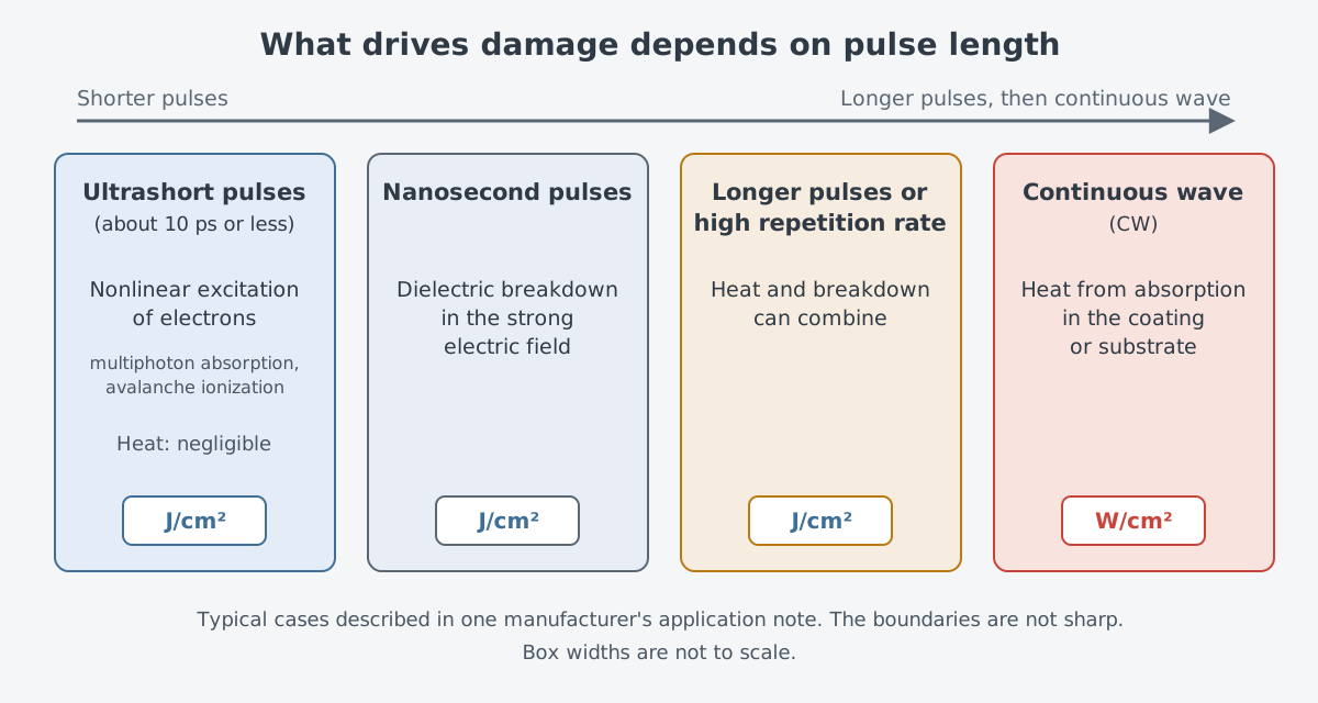
Damage from a continuous-wave laser is usually thermal, caused by absorption in the coating or substrate. Short nanosecond pulses are different. There, damage usually comes from dielectric breakdown driven by the strong electric field in the beam. Dielectric breakdown means current flows through an insulator because the applied voltage exceeds its breakdown voltage.
With longer pulses or a high repetition rate, heat and breakdown can act together. At the other end, for ultrashort pulses of about 10 ps or less, thermal processes are negligible. Instead, nonlinear excitation of electrons, such as multiphoton absorption and avalanche ionization, leads to damage.
Defects and dust lower the threshold
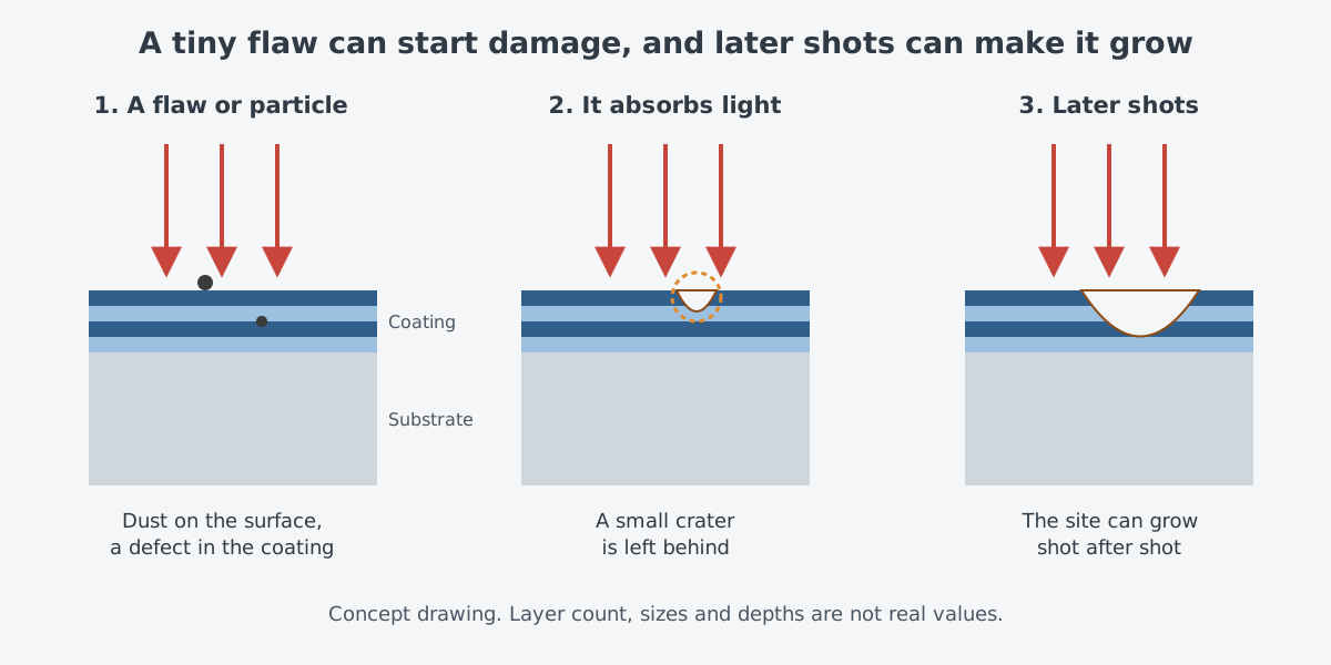
Heat and breakdown are not the whole story. Damage can also start where laser light meets a defect in the part. Such defects include subsurface damage left by grinding and polishing, leftover grains of polishing abrasive, and clusters of metal left from the coating process. The nature and size of a defect set the fluence the part can take.
The layer structure of a coating can itself be a weak point. In structures like the GTI-type mirror from "Mirrors, lenses and coatings," the light's field grows strongly inside the layers. Compared with a standard high-reflectance stack, unwanted nonlinear absorption rises there, and the damage threshold can drop. In a semiconductor saturable absorber mirror (SESAM), poorly controlled defects near the surface tend to degrade the damage threshold, because the field enhancement at the surface lowers it.
Cleanliness also shakes the number a lot. An NKT Photonics note on fiber end faces explains that the damage threshold hinges on how good the end-face surface is. Even small flaws can lower it by several orders of magnitude, and irregularities, roughness and dirt also cut it sharply. The note adds that breakdown thresholds measured in practice can differ by 100 times or more.
Spreading the beam at the end face, for example with an endcap, is another improvement the same note lists. Gratings show something similar. A 2010 LLNL paper studied multilayer dielectric gratings for petawatt-class lasers. It reported that both the profile of the grating lines and how much light-absorbing impurity sits on the surface strongly affect the damage threshold.
How to read an LIDT number
So how should an LIDT value on a spec sheet be read? The Edmund Optics note mentioned earlier points out that there is no industry consensus on how to test LIDT, how to detect damage, or how to interpret the data. As a result, an LIDT value alone does not show the test beam diameter, the shots per test site, or the analysis method.
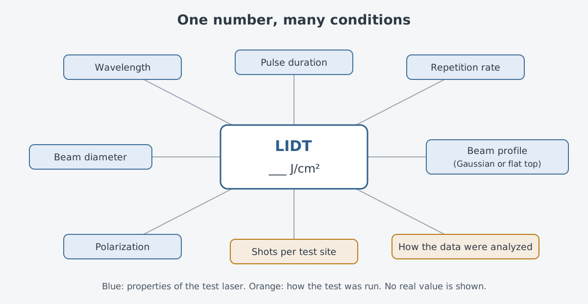
Understanding a pulsed LIDT takes the wavelength, beam diameter, pulse energy, pulse duration, repetition rate and intensity profile. The profile alone makes a big difference. At the same power, a Gaussian beam has twice the peak fluence of a flat-top beam, whose cross-section is even.
NASA's guidelines for one-on-one damage threshold tests carry the same idea. Test reports must give the wavelength, pulse length and polarization of the laser, plus its Gaussian beam profile. They also warn that beams smaller than 1.0 mm across artificially raise the damage threshold found with that procedure.
Sometimes people want to convert a value to a different wavelength or pulse length. Such scaling rules exist, but the Edmund Optics note says to avoid them when possible and not to use them over large wavelength or pulse-length ranges. In one study cited in the NKT note, the damage threshold followed neither the square root of the pulse length nor the pulse length itself, contrary to common belief.
How a large laser facility handles damage
A large laser facility such as LLNL's NIF cannot simply avoid damage. Each time NIF fires, it can cause microscopic exit-surface damage to optics along its beamlines. LLNL says NIF is the world's only laser system run above the damage growth threshold, which lets it deliver extreme laser power.
How does damage start? When flaws, defects or contaminants absorb laser light, they set off a reaction that leaves a crater in the optic. A site on the surface begins very small, often thinner than a hair. With more light, though, a site can grow large enough after several shots to harm the beam's performance.
Surprisingly, the laser itself was a major source of contamination. A 2017 LLNL paper in Optics Express reported that nearly all the damage seen on NIF's fused silica optics came from particle contamination created by the laser. Optics fired five or more times could develop hundreds of damage sites at 8 J/cm², below NIF's full operating value of 10 J/cm².
The researchers coated the exit surfaces of debris shields with an anti-reflection coating developed at LLNL, and added a damage-resistant fused silica screen. Cutting these laser-made particle sources let earlier improvements in optics processing (AMP) show their full effect. More than 98% of the damage to large fused silica optics disappeared at 3 ns pulses and fluences near 9 J/cm². These measures are in use on all 192 NIF beamlines.
Damage still remains. Through the Optics Recycle Loop, its recycling process, NIF routinely removes damaged optics, repairs them and puts them back. The microscopic damage sites themselves cannot be repaired, but they can be stopped from growing under later shots. Shadow cone blockers, first used on NIF in 2019, are one such method.
There are limits. The project's principal investigator explained that only so many repair sites fit on one optic, because the sites scatter light until too little gets through.
From the 1970s Boulder meetings to today
By the early 1970s, optical damage was already a big enough topic for a yearly meeting. On May 15–16, 1973, the 5th Annual Symposium on Laser Damage in Optical Materials met at the National Bureau of Standards (NBS, now NIST) in Boulder, Colorado. The Office of Naval Research (ONR), NBS and the American Society for Testing and Materials (ASTM) sponsored it together.
That year's proceedings mainly covered damage on dielectric surfaces, damage caused by self-focusing, damage in dielectric coatings, and harm to infrared mirrors and windows. The contents include a talk on how coating defects contribute to damage in thin films. It is the same theme as today's point that defects lower the threshold.
Methods for measuring damage kept improving. NASA published its test and certification procedures in a 1997 report, and ISO 21254-1 gained a second edition in 2025 after the 2011 edition. LLNL's NIF work reported new findings on causes of damage and on repair in 2017 and 2024.
Laser weapons and coatings
Laser weapons face the same wall. A beam combining article in the MIT Lincoln Laboratory Journal names one limit of combining systems. The intensity on optical surfaces must be kept under the level that causes damage, and also under the point where thermo-optical effects begin to cause large aberrations.
Coatings are also a production and maintenance issue. The February 2024 update of a Congressional Research Service (CRS) report quotes a fiscal year 2024 budget request. The request covers finishing the development of production capability for "coating chambers for laser weapon optics."
Maintenance shows up in older records too. A 2004 Government Accountability Office (GAO) report looked at an airborne chemical laser weapon prototype. It said the system would need special maintenance, such as recalibrating and re-coating parts of its beam control and fire control systems.
The mirrors and windows inside a beam director are covered further in Beam director optics. The damage thresholds, defects and test conditions in this article apply to those parts too.
What to read next
- "Dichroic Mirrors and Beamsplitters: Splitting Light by Color and Strength": parts that use coatings to split light by wavelength and strength.
- Beam director optics: lenses, mirrors, coatings and a large aperture: what the last optics of a laser weapon must endure.
- Pump and Signal Combiners and Endcaps: Fiber Parts Inside an Amplifier: parts that widen the beam at a fiber end face.