At night, an open field looks plain black to the naked eye. Through an infrared (IR) camera, the same field is full of light and dark patterns. Warm things show up bright and cool things dark. It is a heat picture.
What happens if you put that camera in the nose of a missile? That idea gave rise to the imaging infrared seeker (IIR). This article looks at what a heat picture is made of and what it took to go from one detector to a whole array of them. It then follows the public record of the technology in U.S. missiles and the limits that remain.
One dot or a whole picture
Sidewinder, often named as the first infrared-guided missile, followed the heat of enemy aircraft engines. A history of infrared technology from the Defense Systems Information Analysis Center (DSIAC) notes that the missile owed much to uncooled lead sulfide detector technology. It was a seeker that chased a source of heat.
Chasing heat and "seeing" heat are not the same thing. A single detector turns the infrared that reaches it into one value. To draw a whole scene, you can sweep the detector across it line by line with a mirror. The other way is to lay many detectors side by side like the squares of a checkerboard.
A checkerboard of detectors is called a focal plane array (FPA). The name means an array of detectors placed on the surface where the lens forms its image. Each square becomes a pixel, and the values from all the squares together make one heat picture.
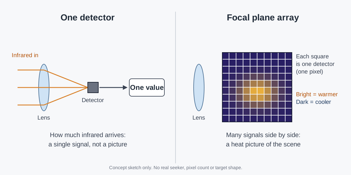
An array can be finer than you might expect. NASA's Jet Propulsion Laboratory (JPL) built a mid-infrared camera for astronomy around 256x256 focal plane arrays. On the missile side, a U.S. Army chronology described the seeker planned for a fire-and-forget version of TOW as a "focal plane array and imaging infrared (FPA/IIR) seeker." Both the array and the image are right there in the name.
A smartphone camera is a useful picture to keep in mind. Like it, the seeker builds one photo from light caught square by square. The differences are real, though: the light an imaging infrared seeker collects is not sunlight bouncing off objects but infrared that the objects give off themselves. And, as later sections show, the detector often has to be kept very cold.
A heat picture is drawn in temperature differences
Infrared is part of the electromagnetic spectrum. The eye cannot see it, but the body feels it as heat. Very hot objects such as a fire also give off visible light, while objects that are not as hot, such as people, give off only infrared. That is why night-vision goggles and infrared cameras can show people and animals on a screen.
This light first became known in 1800. William Herschel put thermometers in each color of the rainbow and measured them. He noticed that a spot just past the red end, where there was no color at all, was even warmer.
What stands out in a heat picture depends less on temperature itself than on the difference from the surroundings. The Johns Hopkins Applied Physics Laboratory (APL) Technical Digest notes that some important targets can be easier to see in the infrared because of thermal contrast. The same article uses a quantity called noise equivalent temperature difference (NEDT). It describes how much warmer or cooler than the background one pixel has to be before its signal rises to the level of the noise.
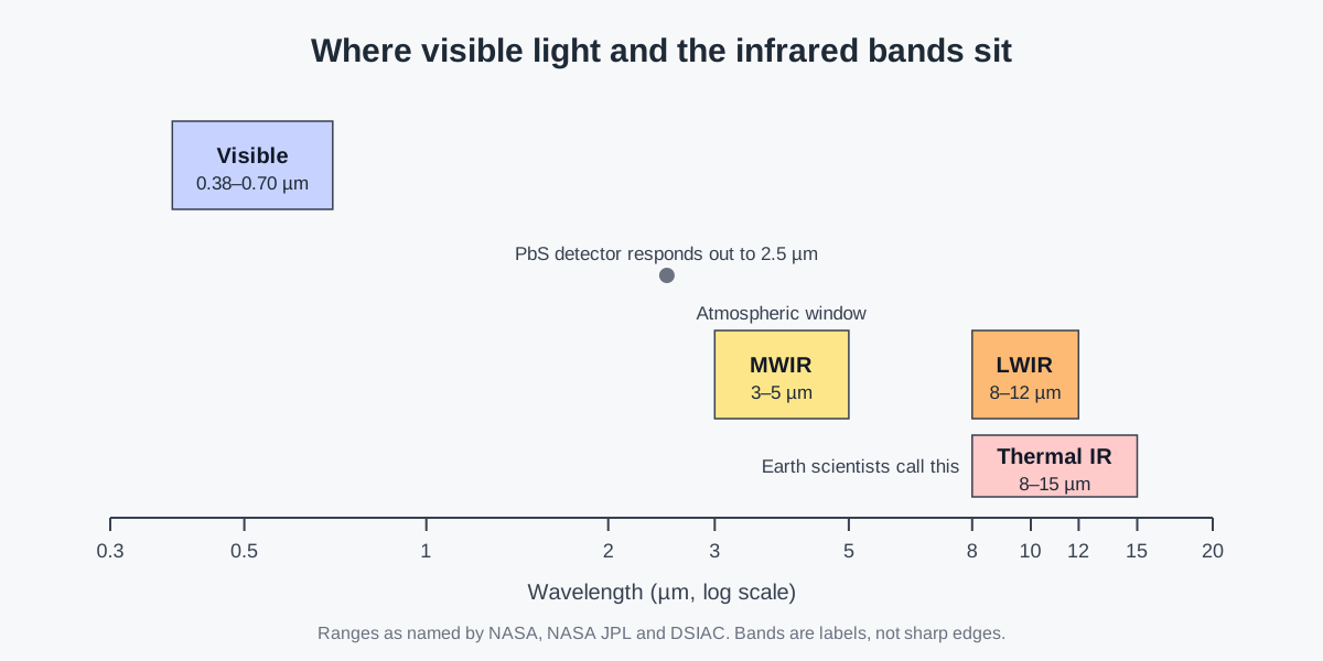
Which wavelength of infrared you look at matters too. The human eye usually sees 380–700 nm. Earth scientists call 8–15 µm thermal infrared, because those wavelengths are best for studying the heat the planet gives off.
Defense infrared work long sought the 8–12 µm long-wave infrared (LWIR) band. For a given temperature difference between an object and its background, this band gives the most signal. The 3–5 µm mid-wave infrared (MWIR) band is another one that NASA JPL calls an atmospheric transmission window.
From one detector to an array
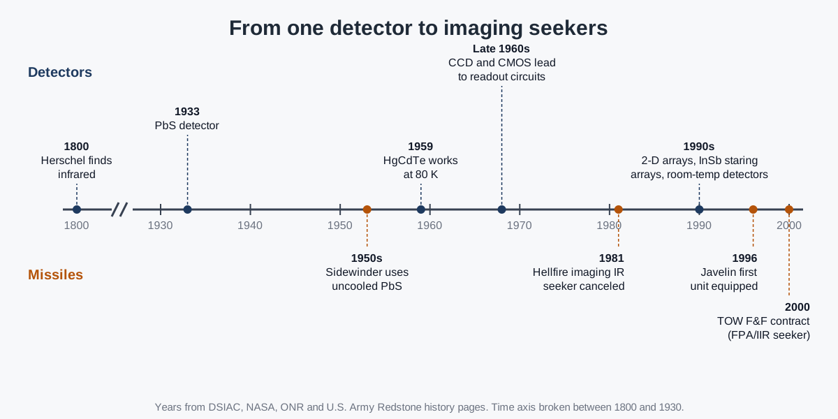
The history of infrared detectors is also a history of materials. In 1933, Edgar Kutzscher at the University of Berlin found that lead sulfide (PbS) could serve as a detector that reacts to light. Lead sulfide reacts to infrared out to 2.5 µm. That let it pick up the light that hot objects, such as a ship's stacks or an engine's exhaust pipes, give off on their own.
The first images were drawn with a single detector: in 1950–1960, single-element detectors first produced images of scenes built up one line at a time. Early infrared mappers of the Vietnam War era also swept one detector over the ground, line by line, with a scanning mirror. Adding a vertical mirror let the detectors sweep in two directions, so the device could look forward instead of down. That is where the name forward-looking infrared (FLIR) came from.
Electronics opened the way to large arrays. With devices such as CCD and CMOS in the late 1960s, a detector array could be tied to readout circuits sitting on the focal plane itself. These circuits are called readout integrated circuits (ROICs).
Without them, every detector needs its own wire and amplifier, and the size of an array is capped by how many wires and amplifiers fit in a practical package. A readout circuit gathers the signals from many detectors and sends them on together, which separated the number of wires from the number of detectors. After that, dense, large arrays became possible.
The payoff came in the 1990s. The U.S. Army got second-generation infrared detectors with large two-dimensional scanning arrays. The Air Force and Navy developed staring arrays made of indium antimonide (InSb), which cost less and respond in the 3–5 µm band.
In the 1990s and 2000s, thermal detectors that work at room temperature also came into wide use. Such a detector acts like a tiny thermometer: its own temperature changes, and that change is read out. It is usually far less sensitive than a cooled detector, but many of them together in a staring array become useful. DSIAC lists missile seekers among their uses, alongside driver night viewers and rifle scopes, and points to their low cost and low power.
An eye that has to be kept cold
Why do you need to cool a detector to see long-wave infrared well? Long-wave infrared photons carry little energy. A detector built to sense this band therefore also picks up dark current made by its own heat, along with the noise that comes with it. In effect, the detector's own warmth hides the signal it is trying to see.
The first practical long-wave detector material, mercury-doped germanium (Hg:Ge), had to be cooled to 30 K to hold down dark current, with large, heavy and expensive coolers. That changed in 1959, when W. D. Lawson of the U.K. Royal Radar Establishment found the benefits of mercury cadmium telluride (HgCdTe, or MCT).
With lower dark current, this material could sense long-wave infrared at a much higher 80 K, and coolers became far smaller, lighter and cheaper.
The challenge has not gone away. NASA JPL regards working at higher temperatures as a major advantage, and it developed a detector that operates at 150 K and covers the whole 3–5 µm atmospheric transmission window. Even with that higher temperature, custom coolers are still needed.
The material itself can be difficult. MCT is soft and brittle, so growing, processing and storing it takes great care, and large MCT arrays tend to be very costly.
Heat pictures inside missiles
One missile family shows a change of "eyes" within the same line. According to the U.S. Navy, the AGM-65 Maverick uses electro-optical guidance, like a TV camera, in its A and B models. Its D, F and G models use imaging infrared, and its E model uses laser guidance. A seeker that takes heat pictures moved into the spot once held by a TV-camera seeker.
Not every attempt went ahead. The U.S. Army's Hellfire chronology at Redstone Arsenal has an entry for February 10, 1981. On that day, full-scale development of a "fire and forget" seeker, an imaging infrared seeker adapted to Hellfire, was canceled. The main reasons were cost and concerns about fitting it to aircraft.
The Javelin anti-tank missile ties straight into the history of detector arrays. In August 1989, an agreement between the Army Missile Command and the Defense Advanced Research Projects Agency (DARPA) was extended. Its purpose was to move DARPA's infrared focal plane array technology into Army missile programs. In September 1990, a focal plane array that met the development specification was delivered to the program.
The program took the name JAVELIN in fiscal year 1991, and on June 27, 1996, the first unit was equipped with it. The Army chronology names fire-and-forget guidance as Javelin's key feature, since it lets the gunner fire and take cover right away. Its listed features include an imaging infrared seeker and target lock-on before launch. How anti-tank missiles took work off the gunner from one generation to the next is covered in Anti-tank guided missiles: rockets versus guided missiles.
How far does "recognizing" go? On September 9, 2000, the Army signed a development contract for a fire-and-forget version of the TOW missile. Under that plan, a focal plane array and imaging infrared seeker, working with software, would track the target automatically and remove the TOW wire. Software reading the heat picture and keeping hold of a target: that is as far as the public record takes the idea of recognition.
Arrays also affect how a seeker is built. Many seekers mount the sensor on a gimbal to widen its field of regard and isolate it from the motion of the missile body. The APL Technical Digest gives a different example, though. Tracking systems that do not need a wide field of regard, or that use an infrared focal plane array, may instead be fixed to the body.
This is called a strapdown design. The gimbaled side of the story is in Missile seekers: the "eyes" at the front of a weapon.
What a heat picture cannot do
A heat picture is good at giving direction but does not give distance. The APL Technical Digest notes that passive infrared imaging systems built for naval defense can estimate target angle very accurately but provide no range data. Such systems are passive sensors: they send nothing out and only take in the infrared that arrives. The same problem, seen from the side of finding aircraft, is the subject of Infrared search and track (IRST): seeing aircraft without sending radio waves.
Weather is a limit as well. In a 1997 report evaluating the 1991 Desert Storm air campaign, the U.S. General Accounting Office (GAO) summarized what pilots reported. In those reports, clouds, rain, fog, smoke and even high humidity badly cut the performance of infrared, electro-optical and laser systems alike. Pilots also said they could not tell if a suspected target was a tank or a truck, or if it was already destroyed.
It is worth remembering that a heat picture is only a picture made of heat. When the temperature difference is small, the difference between pixel values is small too, and it has to compete with the detector's noise. Cooling the detector, enlarging the array and handling costly materials are all efforts to see that small difference a little more clearly.
Where this meets lasers: the same air, the same windows
The GAO report put infrared, electro-optical and laser systems in a single sentence. All three are systems that work with light. When clouds, smoke and moisture blur a heat picture, a laser beam has to deal with them too. Why a beam weakens and spreads in air is explained in Atmospheric propagation: absorption, scattering, turbulence and thermal blooming.
Both fields also face the fact that how well light gets through depends on wavelength. Infrared has longer wavelengths than visible light, so in space it moves through thick clouds of gas and dust while being scattered and absorbed less. Infrared detectors pick atmospheric windows such as 3–5 µm. The laser side has its own story of choosing a wavelength, told in Why wavelength matters: visible and invisible light.
What to read next
- Missile seekers: the "eyes" at the front of a weapon: the overall picture of what a seeker is made of and what it does.
- Infrared search and track (IRST): seeing aircraft without sending radio waves: a sensor that uses the same infrared to find aircraft.
- Anti-tank guided missiles: rockets versus guided missiles: the generations of anti-tank missiles that Javelin belongs to.
- Atmospheric propagation: absorption, scattering, turbulence and thermal blooming: what light goes through in air, seen from the laser side.