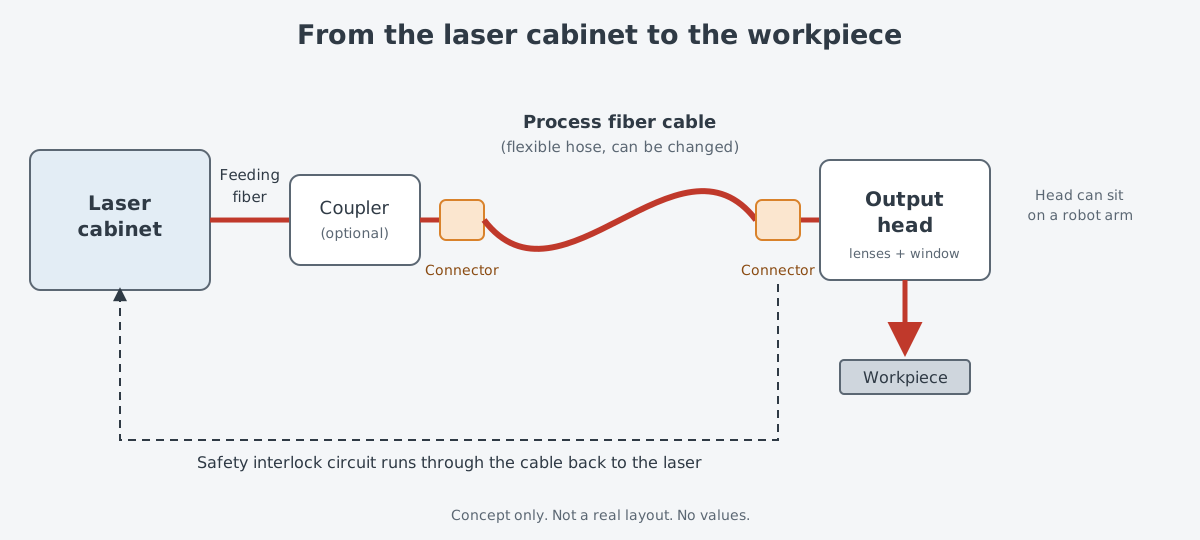
Picture a laser cutting machine in a factory, where the laser that makes the light sits in a cabinet on the floor. The head that sends the light out moves at the end of a robot arm some distance away. A single cable that looks like a thick hose joins the two. What does the spot look like where kW-class light passes through this cable and leaves the glass?
There is a connector at each end of the cable, and the last stop for the light is the output head. This article looks at what sits inside the connector, how the output head gathers spreading light again, and how the shape of these parts settled into standards.
From the laser cabinet to the processing head
The light of a fiber laser is inside a glass strand from the start. A glass fiber has a higher refractive index in the central core and a lower one in the surrounding cladding. Light is totally reflected at the boundary with the cladding and stays in the core, so it travels with little loss. That is why the light follows the cable even when the cable bends.
Industry uses this property directly. A feeding fiber from inside the laser connects to a process fiber cable, and the output head at its end sends light to the workpiece. High-power cables have a reinforced hose to stand up to harsh industrial settings, so they are used for moving robotic work too.
Why the end face is the weak link
While light is inside the glass, things are fairly easy. The trouble is at the end. On the face where the fiber stops, light must leave the glass and enter air, and this end face is easier to damage than the body of the glass.
An application note from NKT Photonics says end faces are usually more fragile, and that unevenness, roughness or dirt on the face sharply lowers the laser-induced damage threshold (LIDT). End faces have to be handled with care to keep them free of scratches and contamination. The note deals with end faces in pulsed lasers. Still, a connector that is plugged in and pulled out on a factory floor is always exposed to dust and scratches, wherever it is used.
Widening the beam at the end face helps the face take more, and an endcap is one way to do it. How an endcap widens the beam and lowers the intensity on the face is covered in Pump and Signal Combiners and Endcaps. High-power connectors carry this block of glass inside them.
What is inside the connector
Cut a connector in half and you find three jobs in one place. There is glass that widens the beam before it leaves, a section that removes unwanted light, and cooling that takes away the heat from that light.
The first is the glass block: Coherent explains that a quartz block inside the connector raises how much power it can handle. Its face can carry an anti-reflection coating for common visible and near-infrared wavelengths. The datasheet's feature list also names an AR-coated end cap. End caps meant to carry kW-class beams are also made with glass and coatings that absorb little light.
The second is the cladding light stripper, or mode stripper. Light leaking along the cladding outside the core blurs the beam.
The stripper inside the connector removes three kinds of light. They are pump light that was not used, laser light that may have entered the cladding through misalignment, and light reflected back from the workpiece. Removing this light cleans up the beam so it can be focused better on the work surface. The principle of the stripper is the subject of "Cladding Light Strippers: Where Leftover Pump Light Goes."
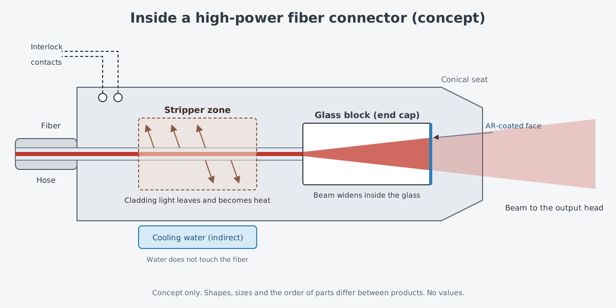
The third is cooling. The energy of the stripped light stays in the connector and has to go somewhere, so thermal management becomes a large part of the connector's job. Coherent cools its QBH connector with water and says this raises its ability to handle the power it loses. An air-cooled version (RQB) also exists for lower-power systems.
A design released in 2021 uses indirect water cooling, where the water never touches the fiber directly, and the company says this relaxes the demands on cooling water quality. The 2017 release on the air-cooled version states that the connector includes a temperature switch that guards against overheating.
Safety interlocks: checking that the fiber is in place
A connector is not only a path for light. An electrical circuit runs through it too, and that circuit is the safety interlock.
The US federal regulation 21 CFR 1040.10 defines a safety interlock as a device tied to a laser product's protective housing that keeps people from reaching excessive radiation. The regulation requires laser systems in laser safety class IIIb and IV to have a remote interlock connector. When the terminals of that connector are not electrically joined, people must not be able to reach laser radiation above the Class I limits. What the classes mean is covered in Laser safety: classes and how to read eyewear labels.
That definition in the regulation concerns protective housings and remote interlock terminals. A fiber connector has its own interlock circuit, added by the manufacturer. Coherent's receiver locks the cable connector in place and engages the fiber safety interlock circuit automatically. The 2017 release says this interlock keeps watching the status of the fiber.
Some devices watch with light as well. A connector called QD contains a photodiode, according to the company. It can sense coupling losses where light goes in, and light bouncing back from the workpiece where it comes out.
The output head: gathering spreading light again
Light leaving the connector spreads out widely. The output head's job is to gather it again into a small spot on the workpiece. According to the optics maker Ophir, the output optics of fiber beam delivery usually have three parts: a lens that collimates, a lens that focuses, and a window that protects.
The collimating lens catches the strongly spreading light from the fiber and turns it into a parallel beam with less spread. The focusing lens then brings this parallel beam to a point, and that point is an image of the end face of the fiber. What lenses themselves do is covered in Mirrors, lenses and coatings, and parts that straighten a beam in "Collimators and Beam Expanders: Straightening and Widening a Beam."
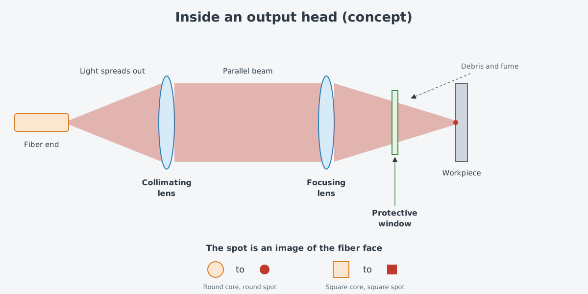
Saying the spot is an image of the end face has a real meaning. The shape of the spot follows the shape of the core. QBH cables come with round or square cores, and the 2017 release says a square cross-section core gives a square beam with an almost flat top.
The last part, the protective window, is a consumable. No nozzle is perfect, so debris, fume and spatter can reach the lens. That is why most fiber laser systems put a protective window just ahead of the focusing lens, shielding it from the metal being cut. This window is the optical part replaced most often in fiber laser systems.
Devices for swapping fibers
Process fibers are also parts that get swapped. Different uses need different beams, and a fiber can be damaged at the work site. So a device that hands light over between two fibers sits between the laser and the head.
Fiber couplers often serve to shield the laser and its feeding fiber from what happens at the work site. Placing a coupler ahead of the beam delivery head also makes fibers easy to change. That lets the beam be adjusted quickly for a different use, or a damaged fiber be replaced.
A beam switch goes one step further. It lets one laser send light to up to six process fibers at several work stations. In time sharing, only one beam goes out at a time. In energy sharing, the laser's energy is split and sent to several stations at once.
There are also cables for when connector shapes do not match. A hybrid cable with a different connector at each end links a laser and a head whose fiber connections differ, without an extra adapter.
How standard interfaces took hold
The very existence of hybrid cables means connector shapes vary. A few of them have settled into common shapes across the industry.
The most common is QBH. Coherent describes QBH as the standard fiber connection across the industry for high-power fiber lasers in factories. It says the proven design fits many laser processing systems and tools around the world.
The 2017 press release notes that Coherent was formerly Optoskand AB. That same year, a cable came out that kept the standard QBH interface but was cooled by air.
In 2021 an indirect water-cooling design followed, and the company said it raised the maximum rating to 15 kW continuous wave for use with infrared fiber lasers. Another shape, QD, meets the standard interface requirements of the European automotive industry, and its datasheet lists up to 20 kW continuous wave. Once a connector shape becomes a standard, a laser from one company and a head from another can still fit together.
The same trend shows up in parts for high energy lasers (HEL). FiberBridge Photonics in Germany offers one- and two-dimensional arrays of fiber connectors for multi-beam uses with high optical power, and says each channel is kW-class and uses industrial connectors. It lists high energy laser pumping, coherent beam combining (CBC) and spectral beam combining (SBC) among the uses. The chain of parts that makes up one laser weapon is traced in Following One Laser Weapon.
What to read next
- Pump and Signal Combiners and Endcaps: Fiber Parts Inside an Amplifier: how the glass block in the connector protects the end face.
- Isolators and fiber components: keeping light from going backwards: why light coming back from the workpiece is a problem inside the laser.
- Laser safety: classes and how to read eyewear labels: the laser classes that the interlock rules rely on.