Picture a fighter cockpit low over the ground at high speed. In the moment it takes to glance down at the panel for speed and altitude, the view outside changes a lot. To shorten that moment, aircraft have moved information up to the pilot's eye level, and then onto the pilot's helmet.
A helmet-mounted display (HMD) puts a small screen and optics on the helmet, so information and imagery stay before the pilot's eyes wherever the pilot looks. This article covers what parts an HMD is made of and why the image is set far away rather than right in front of the eye. It also traces how the device developed and what is still hard about it. It follows a public book from the U.S. Army Aeromedical Research Laboratory (USAARL).
The seconds spent looking down
A screen you look down at, like the instrument panel, is called a head-down display. The USAARL book notes that in fast aircraft that fly low over the ground, even the brief glance down at the instruments may severely degrade situation awareness. Switching between the panel and the outside view keeps interrupting the flow of information, and moving the eyes and head and refocusing all take time.
That drawback led to the head-up display (HUD). A HUD uses a clear glass or plastic pane fixed just behind the windscreen. The pilot keeps looking outside, head up, and reads key flight data reflected on that pane at the same time.
A HUD is fixed facing forward, though. When the pilot has to keep turning the head to search the sky, it helps less. That limit played a large part in the idea of mounting the display on the head itself.
Four parts of a helmet display
In its shortest definition, an HMD is an image source and collimating optics in a head mount. U.S. Army rotary-wing aviation adds a head tracker and counts four parts: the image source, the display optics, the helmet and the head or eye tracker.
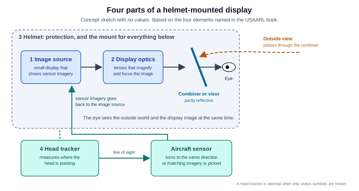
The image source is a small display that reproduces sensor imagery. Early ones used tiny cathode-ray tubes (CRTs) or image intensifier tubes. The display optics magnify and focus that image and send it to the eye. The helmet keeps its original job of protection and also becomes the mount for the image source and the optics.
The last part in front of the eye is a partly reflective element called a combiner. The outside world shows through the combiner, while the image from the source reflects off it into the eye. It is a bit like looking out a window at night from a lit room, when the outdoor scene and the reflected room overlap. A real combiner differs because it is an optical part built to show a set image in a set place, not a chance reflection.
Some designs use the visor itself instead of a separate combiner. Optics carry the image from a source on the top or side of the helmet onto the visor, and the visor reflects it back to the eye. Visor projection is lighter, improves the center of mass, leaves more room between the eye and the optics, and blocks less of the view. Ghost images, where a faint second copy of the image appears, can be a problem, though.
Why the image is set far away
What happens if you simply put a small screen a few centimeters from the eye? The eye then gets spreading light, the kind that comes from a nearby object. A tiny liquid crystal screen viewed directly could not sit any nearer than reading distance, and that does not work on a helmet.
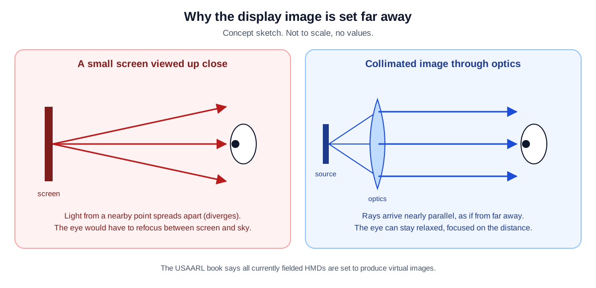
So the optics make the image look as if it were far away. An image formed this way, not on a real screen, is called a virtual image, and the HMDs fielded when the book came out in 2009 all produced one. A virtual image near optical infinity can, in theory, let the eye relax and reduce fatigue, and it makes focusing easier for older users.
Compare it with reading at a desk and then looking out the window at a distant hill: the eye needs a moment to refocus. When the display image sits far away like the outside scene, that switch shrinks. The real effect varies from person to person, though. A virtual image lets more people use the system without corrective lenses, but not everyone.
An image set far away has a bonus. A collimated image, one that arrives as nearly parallel light, reduces the retinal blur caused by vibration. Fighter HUDs are also normally set with focus and alignment close to infinity, so they line up with distant objects outside.
A sensor that follows the head
If the display shows only flight status, it does not need to know where the helmet points. Showing sensor imagery of the outside is different. The system has to keep recalculating where the pilot is looking and either turn the aircraft's sensor that way or pick imagery that matches that direction. A head tracker does this job.
The military often calls a head tracker and helmet display working together a visually coupled system (VCS). The direction of the head becomes an input to the sensors and aircraft systems, and the helmet display returns the result as symbols and imagery. Before flight, a calibration called boresighting lines up the sensor's line of sight with the user's. Head tracking adds cost and complexity to an HMD.
A good example is the IHADSS of the AH-64 Apache. An infrared head tracker on the helmet follows the pilot's head movements and turns a forward-looking infrared (FLIR) sensor on the nose in the same direction. That imagery appears in the helmet display together with flight symbols such as heading and altitude.
Displays also differ in how many eyes see the image. Monocular means one eye sees the imagery. Biocular means both eyes see exactly the same image, and binocular means each eye gets its own image from two separated sensors, which gives depth. The IHADSS is monocular.
From a patent to the fighter cockpit
Officially, HMD history begins with Albert Bacon Pratt, a chemical engineer from Vermont. Between 1915 and 1917, during World War I, Pratt received U.S. and U.K. patents for a helmet aiming device for a marksman. That sight was never fielded.
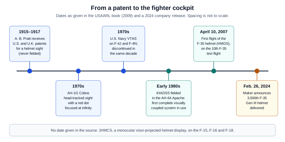
An early example that did see use was a 1970s helmet sight on the AH-1G Cobra, an attack helicopter of the U.S. Army. A mechanical linkage followed the head, and a small semi-transparent window before the right eye showed a red dot. The dot was focused at infinity, much like the simple red dot sights found on some pistols and rifles.
Not long after the Cobra sight, the U.S. Navy added VTAS, a head tracker that worked electro-optically, to its F-4J and F-4N Phantom fighters. VTAS was dropped in that same decade because of its technical limits.
The turning point was the AH-64 Apache. Until then, the main job of an aviation helmet was protection from impact and noise.
The new attack helicopter the U.S. Army fielded in 1981 needed the helmet to link the aviator and the aircraft. Honeywell developed the IHADSS in the late 1970s, and it came into use in the early 1980s. The book calls the IHADSS the first complete visually coupled system to see operational use, and the first HMD whose helmet and optics were developed together as one system.
Helicopters did much to win acceptance for HMDs. In a helicopter, the HMD does not have to cope with high-G maneuvers or the wind blast of an ejection. On the fixed-wing side, the U.S. Air Force and Navy added JHMCS, a monocular visor-projected display, to the F-15, F-16 and F-18.
The F-35 helmet (HMDS) first flew on April 10, 2007, on the 10th F-35 test flight. In 2009, the book already described the F-35 as the first tactical fighter without a dedicated HUD, leaving that role to the helmet.
The helmet comes from a joint venture of Collins Aerospace and Elbit Systems of America. On February 26, 2024, that company announced it had handed over its 3,000th Gen III helmet for the F-35. It describes the helmet as the pilot's primary display, showing flight, tactical and sensor information by day or night.
Heavy, a little late, and hard to look away from
Is it always good to have information floating in front of the eyes? The gains from a new HMD always come at a cost. If an HMD demands an unacceptable compromise in something critical to the mission, it ends up unused.
The first cost is weight. A civil pilot's headset usually weighs 340–510 g, while an HMD adds at least 454 g to the load the head carries. Helmet-based HMDs for military pilots weigh more than 1.8 kg.
Because the optics must sit before the eye, the extra weight tends to sit above and ahead of the natural center of mass of the head. Over a long flight, that may lead to muscle fatigue.
The second cost is latency. Measuring the head position, passing it to the sensor, turning the sensor to the new direction, capturing the scene and showing it in the helmet all take time. According to the book, this delay is typically hundreds of milliseconds, and the largest part is the time the sensor takes to turn.
Studies cited there found that delays near one third of a second (about 300 ms) or longer are unacceptable for performance. These delays have also been named as a cause of motion sickness.
The third set of problems comes from the HUD. One is attention capture, where the pilot pays too much attention to the display and too little to events outside. Attention capture with HUDs just inside the windscreen has been blamed for missed runway incursions. Symbols or imagery can also hide important objects outside, so keeping symbols few and within a recommended size is one listed fix.
Where this meets lasers: following a line of sight
The head tracker in an HMD measures where a person is looking and turns an aircraft sensor that way. Measuring a direction and turning something to it are tied together in one loop.
Laser weapons face a similar task. A beam director rides on a two-axis mount called a gimbal, changing azimuth and elevation to hold the beam on one distant spot. That story is in Gimbals, pointing and tracking: holding the beam on one spot. One turns an infrared sensor and the other a laser beam, but in both cases a slow or shaky tracking loop causes problems.
What to read next
- Infrared search and track: seeing aircraft without emitting: how an infrared sensor picks out aircraft in the sky.
- Gimbals, pointing and tracking: holding the beam on one spot: measuring and following a direction, seen from the laser beam side.
- Mirrors, lenses and coatings: optics for strong light: the basics of optical parts that reflect and pass light.