To anyone trying to push a fiber laser to higher power, the core always feels too narrow. When light stays packed into a thin core over a long distance, nonlinear effects show up first as the power climbs. In pulsed operation especially, they can spoil the pulse shape in time, the spectrum and the beam profile all at once.
The fix looks simple: make the core wider so the light spreads out. But the moment the core gets wider, the light no longer travels in just one shape. Keeping a clean beam in a wide core takes careful fiber design.
Those designs grew along two paths. One reshapes ordinary glass fiber by coiling it or adding structure to the cladding. The other drills air holes into the cladding, which leads to the photonic crystal fiber (PCF). The sections below follow both paths, where they meet, and where they ran into walls.
What happens when the core gets wider
Among the nonlinear effects in a fiber, self-phase modulation (SPM), stimulated Raman scattering (SRS) and stimulated Brillouin scattering (SBS) are set by how intense the light in the core is. At the same power, light spread over a larger area has a lower intensity, so these effects get weaker. A 2012 paper on large-mode-area fibers calls scaling up the mode area, and with it a sharp drop in intensity, the most effective remedy.
Think of a garden hose. Send the same flow of water through a thicker hose and the stream loses its force. In a real fiber, though, the light is not spread evenly across the core. It forms a peak that is highest in the middle, so the relevant size is the area the mode actually fills.
There is a second benefit. A wider core usually makes a design that absorbs pump light more strongly, so the active fiber used for amplification can be shorter. A shorter path means weaker nonlinear effects again.
The approach works for both continuous-wave and pulsed operation. It only helps, however, against effects that depend on intensity.
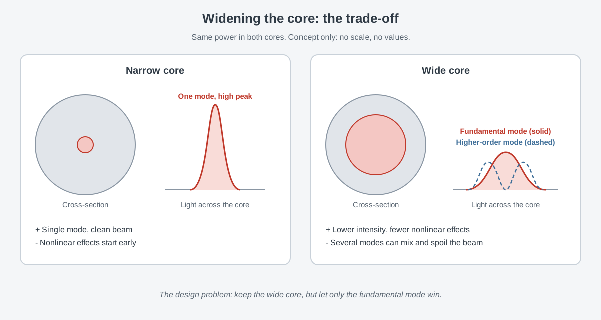
The price is extra modes. Scaling up the mode area unavoidably lets the core carry several modes. When several transverse modes overlap, the spectrum ripples, beam quality drops, and the direction the beam points becomes less steady.
So where does "wide" begin? According to the 2012 paper, the single-mode limit of a conventional step-index fiber is about 15 μm at a wavelength of 1 μm. A fiber whose mode size goes beyond that limit is a large-mode-area fiber (LMA).
Keeping one mode in a wide core
Removing higher-order modes from a wide core entirely is hard. So the goal shifts a little: let higher-order modes exist, but make sure the fundamental mode dominates at the fiber's output. This is called effective single-mode operation.
The simplest method is matched excitation. The seed light going in is shaped to fit the fundamental mode, so only that mode gets excited from the start. As the mode area grows, exciting just one mode becomes harder and harder.
The second method is bending. When a fiber is bent, higher-order modes lose more power than the fundamental mode. In a 2000 Optics Letters paper, Koplow, Kliner and Goldberg coiled a multimode amplifier made from ytterbium-doped double-clad fiber. The coil gave strong bend loss to every mode except the lowest-order one.
Run as a source of amplified spontaneous emission, the amplifier produced an output beam with an M² of 1.09±0.09. The 2012 paper, however, says the bending effect fades as the core grows, which keeps this method to cores smaller than 30 μm.
The third method is resonant filtering. If the cladding contains structures that match the higher-order modes, those modes leak out of the core and are filtered away along the fiber. Chirally coupled core fibers and Bragg fibers are examples.
Resonant designs are very hard to make because their tolerances are tight. They can also fail when the transmission band is narrow or when pumping and bending shift the effective index.
A cladding made of air holes
In October 1996, Knight, Birks, Russell and Atkin reported a new kind of waveguide in Optics Letters. It had a pure silica core surrounded by a hexagonal pattern of silica and air, and they called it a photonic crystal fiber. It guided a single low-loss mode over a broad range of at least 458–1550 nm.
Hamamatsu Photonics, a manufacturer in this field, also dates PCF to 1996 and credits Philip Russell of the University of Bath. The company says it has been central to developing and commercializing PCF since 1999.
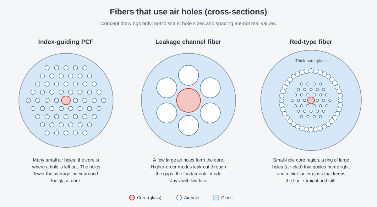
The structure works like this. Fine air holes run along the full length of a glass strand, and the core sits where one hole is left out. In an index-guiding PCF with small holes, the structured region has a lower average refractive index than the glass core. Light is therefore trapped in the core, much as in an ordinary fiber.
In 1997, Birks, Knight and Russell went a step further. Using an effective-index model, they showed that such a fiber can be single-mode at any wavelength. The paper's title called it "endlessly single-mode."
That phrase comes with a condition. Within the range where silica is transparent, the usable single-mode range is wide, but it ends at a bend-loss edge on both the short-wavelength and the long-wavelength side.
For lasers, the appeal of PCF lies in index control. To widen the mode in a step-index fiber, its numerical aperture (NA) must be lowered, and that has technical limits. An index-guiding PCF lets designers set the index far more precisely, so a very low numerical aperture becomes possible and the mode area can grow further.
Larger holes bring in a different principle. Higher-order modes have finer patterns, so they slip out through the gaps between large holes more easily, while the fundamental mode stays. This idea is called a "modal sieve."
The leakage channel fiber reported by Dong, Peng and Li in JOSA B in 2007 belongs to this family. A few large air holes form the core, and the design gives higher-order modes a large leakage loss while keeping the fundamental mode's loss very small. The large holes also make the fiber resistant to bending, and the authors showed the potential to carry a fundamental mode in cores more than 100 μm across.
There is a drawback. The approach relies on a cladding that lets light leak out, and the double-clad fibers used for high-power pumping usually lack one.
Air holes can also leave the core empty. The University of Bath research portal lists a paper by Cregan and six co-authors in Science, dated September 3, 1999: "Single-mode photonic band gap guidance of light in air." As the title says, it guided light in a single mode through an air core using a photonic band gap.
In a 2003 Science paper, Russell wrote that PCF goes beyond the limits of conventional fiber, for example with low-loss guidance in a hollow core. In his view, this brought a renewed wave of interest in optical fibers.
Bending shrinks the mode: rod-type fibers
Making the core very large brings a new problem. When such a large fiber is bent, the mode shrinks and the mode area gained by the design is lost. This happens in every type of fiber, and it gets worse as the core gets larger.
It seems like common sense that a fiber is something you coil. The rod-type fiber drops that idea. The fiber is made as a stiff rod and is not bent at all. Early rod-type ytterbium-doped PCFs were the first examples of very-large-mode-area fiber.
A rod-type fiber shows three layers in cross-section. In the middle is the core region, surrounded by small air holes. Around it, a ring of very large air holes forms the air-clad, which holds the pump light.
The outermost layer is thick silica glass. It makes the fiber stiff enough to support itself without the polymer coating of ordinary fiber. That coating is also one of the main sources of heat-related degradation in high-power fiber lasers and amplifiers.
The gains were large. Early rod-type designs pushed fiber laser performance up sharply, especially in pulsed operation, and the stiff shape kept the large mode area along the whole fiber.
The limits were clear too. Making the tiny hole pattern the same way every time was very hard, which meant low yield and high cost. Early rod-type fibers carried a few modes, so the fundamental mode had to be excited with care. At very high power the beam often degraded or became unstable, and the fibers did not come into wide use.
Designs that push higher-order modes away
Most of the methods so far try to remove higher-order modes by making them lose power. There is another idea: instead of destroying higher-order modes, move them out of the region that amplifies light.
A 2020 review of TMI sorts effective single-mode designs into two groups this way. Designs that add high propagation loss or create a photonic band gap try to wipe out higher-order modes. Designs that couple them selectively to neighboring cores, or delocalize them, try to clear them out of the active region.
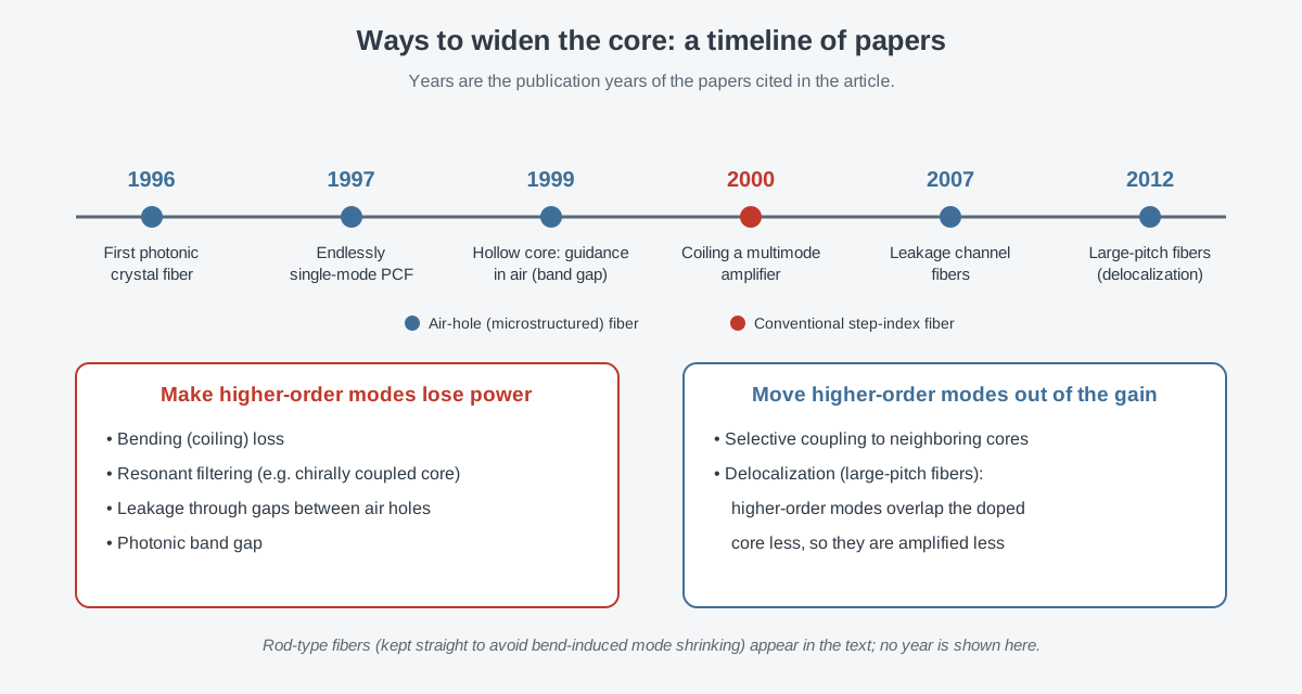
The first example of delocalization is the large-pitch photonic crystal fiber (LPF). As the name suggests, the air holes are spaced far apart and the inner structure is fairly open. Higher-order modes are strongly distorted there and overlap poorly with the ytterbium-doped core region. Only the fundamental mode keeps a near-Gaussian shape with a large overlap with the core.
Higher-order modes are therefore amplified less than the fundamental mode, an effect called preferential gain. The incoming seed light is usually near-Gaussian too, so it mainly excites the fundamental mode.
There are two advantages. The LPF is one of the simplest PCF structures, so it is fairly easy to make and gives a high yield. And a ytterbium-doped rod-type LPF can be an effectively single-mode fiber with a mode size more than 100 times the wavelength of the guided light. The 2020 TMI review counts delocalization among the most successful approaches for fibers with a mode-field diameter above 50 μm.
What remains after widening
Widening the core revealed another wall. As fiber laser output grew, the heat load grew sharply too, and thermal effects appeared in the active fiber. One is a mode diameter that shrinks as average power rises.
A smaller mode makes nonlinear effects stronger again and cancels part of the benefit of the wide core. The other is transverse mode instability (TMI), covered in an earlier article.
Here delocalization helps again. Fibers that delocalize modes have a TMI threshold 2–3 times higher than conventional designs of similar size. Less light sits in higher-order modes at the start of the fiber, and those modes are not amplified as well as the fundamental mode. TMI does not disappear; its threshold only moves up.
Manufacturing remains hard as well. The tight tolerances of resonant designs and the low yield of early rod-type fibers are examples. And by refusing to bend, a rod-type fiber became something that cannot be coiled the way ordinary fiber is.
These fibers are used widely. An ultrafast laser textbook names supercontinuum generation, which broadens the spectrum strongly, as one of the most important uses of air-hole fibers. It also describes a large-mode-area PCF and a gas-filled hollow-core PCF used to compress pulses at high average power.
The abstract of a 2013 Nature Photonics review notes that many industrial, defense and scientific applications need the high average power and beam quality of fiber lasers. It adds that this success came from work to get past many limits of the fiber architecture. Ways to get more power by combining light from many fibers are covered in Why beam combining is needed, and its three approaches.
What to read next
- How a fiber guides light: core and cladding: the basics of core, cladding, modes and numerical aperture.
- Double-clad fibers and how pump light gets in: the pump-light path that the air-clad takes over.
- Limits of a single fiber (1): nonlinear effects (SBS, SRS): the first wall that pushed cores wider.
- Limits of a single fiber (2): heat and mode instability: the second wall that remains in a wide core.
- Polarization-Maintaining Fiber: Keeping Light's Orientation Fixed: the next fiber component in the series.