Picture a laser marker cutting a serial number into a metal part. The light spot has to follow every stroke of every letter. One way to move that spot is not to move the laser at all, but to put a small mirror in the beam's path and turn the mirror.
The device that turns the mirror is a galvanometer scanner, or galvo for short. One mirror bends the beam along only one direction, so drawing on a plane usually takes two mirrors in a row. The same device moves the beam inside laser microscopes in life science labs and inside metal 3D printers.
The name comes from an old instrument for measuring electricity. This article starts with that instrument's job on the 1858 Atlantic telegraph. It then opens up a modern scanner, shows how two mirrors cover a plane, and compares the galvo with the fast mirror found in articles on laser weapons.
A name borrowed from a current meter
A galvanometer is an instrument that picks up and measures small currents in a circuit. A coil hangs between the poles of a permanent magnet, free to pivot, and a needle is fixed to the coil.
Send current through the coil, and it makes a magnetic field of its own. That field pushes against the magnet's field and produces a turning force, or torque, on the coil. The needle's swing is proportional to the current in the coil. Reverse the current, and the coil swings the other way.
The first galvanometer was built by Johann Schweigger, a German mathematician and physicist. According to teaching material from the US National High Magnetic Field Laboratory (National MagLab), he called it a "multiplier."
That is why today's scanner still carries the galvanometer's name. Both use current to make a torque that turns something by a set angle. In the scanner, a mirror simply takes the needle's place.
1858: shining light on a mirror
Galvanometers with a mirror instead of a needle were already receiving signals from across an ocean in 1858. One example is Thomson's mirror galvanometer in the Science Museum Group collection in London. White and Barr of Glasgow made it in 1858, and its job was to pick up the very faint currents that arrived through a long undersea cable.
Here is how it works. A small bar magnet is glued to the back of a mirror, and the pair hangs on silk threads inside the coil. Light aimed at the mirror bounces onto a marked card set well back from it. Even a tiny turn of the mirror sends the light spot a long way across the marks.
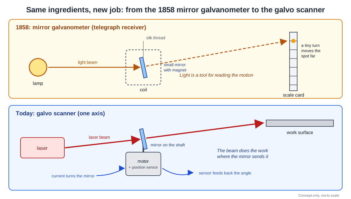
The museum record says this instrument sat on Valentia Island, at one end of the 1858 cable across the Atlantic, and received signals sent from Newfoundland. Less than a month later, the cable stopped working.
The mirror galvanometer went on to become the usual receiver for telegraph messages, but it took two people to run. One read the signal and called it out, and the other wrote the message down. Thomson later solved this with his siphon recorder.
A light beam, a small mirror and a torque made by current. A modern galvo scanner uses the same ingredients. What has changed is the job of the light. In 1858 the light was a tool for reading the mirror's motion; today the laser beam does the work itself wherever the mirror sends it.
One motor, one mirror, one position sensor
One axis of a modern galvo scanner has three parts. There is a galvanometer-type motor, a mirror fixed to its shaft, and a position detector that tells the control board which way the mirror points right now.
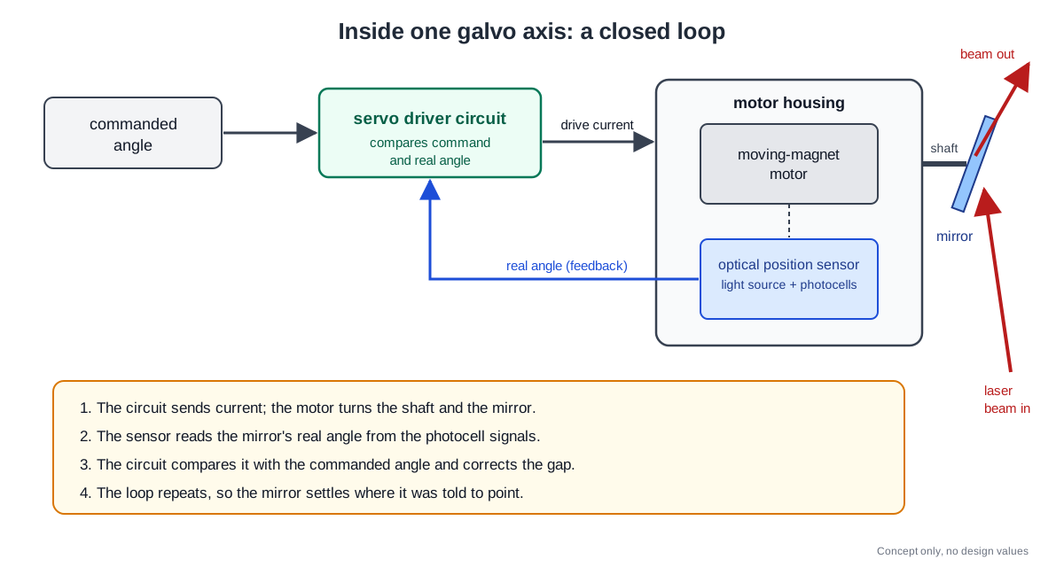
The motor is sometimes built the other way around from the old meter. One product line from Thorlabs, a maker of lab optics, uses a moving magnet instead of a fixed magnet and a turning coil. The company says it chose this to get the fastest response and the highest resonant frequency. The motor section of galvanometer scanners from SCANLAB, a German scanner company, is also based on moving-magnet technology.
The mirror is not just any mirror. The shaft turns with very large angular acceleration, so the mirror's size, shape and inertia become key factors in performance. Even under that hard shaking, the mirror has to stay rigid and flat.
SCANLAB matches each motor to the inertial load of its mirror. The mirrors carry an optical coating suited to common wavelengths and laser powers. The rotor turns on axially preloaded precision ball bearings that keep it free of play.
The position detector sits inside the motor housing. In the Thorlabs product, a small light source and an array of photocells share that housing. Each mirror direction gives one unique ratio between the photocell signals, so reading that ratio tells you the mirror's angle.
This is where feedback begins. A servo driver circuit reads the position detector's signal and produces the drive voltage needed to turn the mirror to the commanded position. Working this way, by comparing the commanded angle with the real one and correcting the gap, is called closed-loop operation.
How fast is it? Take that Thorlabs product, made for beams smaller than 5 mm across. Its mirror can swing across its whole ±12.5° mechanical range 250 times a second with a sine-wave command, or at 100 Hz with a square-wave command.
A small 0.2° step settles at the commanded position in 300 μs, and it can resolve angles as small as 0.0008°.
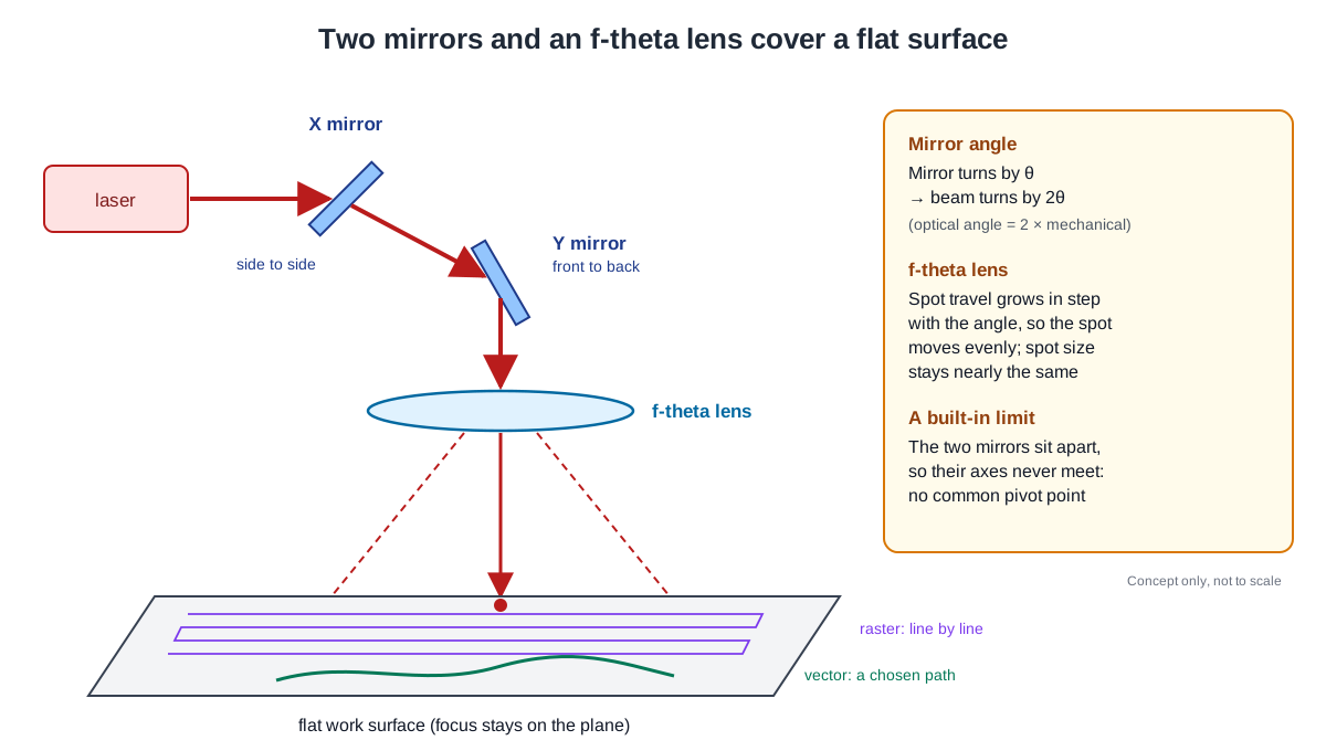
There is one more reason the mirror only needs to turn a little. When a mirror turns by some angle, the reflected beam turns by twice that angle. So a mirror with a mechanical range of ±12.5° sweeps the beam over an optical range of ±25°.
Two mirrors reach anywhere on a plane
One mirror bends the beam in only one direction. To send the beam to any point on a plane, two mirrors that turn on axes at right angles are placed one after the other. One mirror moves the beam side to side, and the other moves it front to back.
The laser scanning confocal microscope is a good example. It builds a digital image by sweeping a focused laser beam across the specimen, back and forth and line by line. A tutorial from Evident, a microscope maker, describes how modern instruments make this pattern with two mirrors driven by galvanometer motors.
One mirror handles the x axis and the other handles the y axis. When their motion is coordinated, they trace a rectangular raster pattern that sweeps one line after another. The scanning speed is set by how fast and how far the mirrors swing.
Raster is not the only way. In vector scanning, the beam follows a chosen path directly. Thorlabs' product description gives laser marking as an example of vector positioning, and printing and scanning laser microscopy as examples of raster positioning. Some uses also stop at one point and then step to the next.
Behind the mirrors, one more lens is needed. Its job is to focus the beam into a small spot on the work surface. Laser scanning and engraving usually need a flat focal plane, but with an ordinary flat-field scan lens the spot's travel is not proportional to the angle the mirror turns.
An f-theta lens fixes this in the glass itself. It is designed with a deliberate barrel distortion so that the spot's travel becomes proportional to the deflection angle. The spot then moves evenly as the mirror turns, with no complex electronic correction, and the spot size stays nearly the same across the whole surface.
Two mirrors also bring a limit that cannot be avoided. Because the mirrors sit apart, their two rotation axes can never meet at one point, so there is no common pivot. Relay optics that image the first mirror onto the second can solve this, but at much greater complexity and cost.
What it does in factories and labs
One factory use is the laser marking described above. For a wider look at cutting, joining and marking with lasers, see "Where industrial lasers are used: cutting, welding, marking, cleaning."
Galvos also work inside metal 3D printers. The US National Institute of Standards and Technology (NIST) ran one 3D build on July 8, 2018, on its Additive Manufacturing Metrology Testbed (AMMT). It published the data in its research journal. The process is laser powder bed fusion, in which a laser melts a bed of powder to build up a part.
The testbed's commands are based on a command protocol for laser and galvo systems. They set the X and Y position for the galvos and the laser power together, 100,000 times a second (100 kHz). A camera that watches the pool of molten metal, the melt pool, is lined up optically with the laser axis. As a result, the melt pool seems to hold still in the camera's view no matter where the galvos point in X and Y.
Something similar happens in the lab microscope. Fluorescence from the specimen travels back along the same path it came in and passes through the two mirrors again. At the pinhole in front of the detector, the light does not follow the scan pattern; it stays in place and changes only in brightness. This return trip is called descanning.
Mirror size depends on the job. SCANLAB offers galvanometer scanners whose mirror apertures range over 6–30 mm. For its small 3–6 mm models, the company lists typical uses as confocal microscopes, biomedical and eye imaging, and medical treatment with lasers.
Companies also grew up around scan heads that package galvos together. SCANLAB's company timeline records that in 1990, the year Hans J. Langer founded the firm in Planegg near Munich, it developed its "first scan head with integrated control."
How it differs from a fast steering mirror
Articles on laser weapons feature another fast mirror, the fast steering mirror (FSM). A lab FSM from Newport also tilts its mirror with torque from coils and feeds back the angle from a position sensor in the mirror head. Open it up, though, and three differences from a galvo stand out.
The first is the number of actuators. That FSM spreads four actuators over the back of the mirror, one per quarter. Their combined force turns large mirrors better than the single actuator in a galvanometer scanner.
The second is the support. The galvos described above hold the rotor on ball bearings. The FSM holds its mirror on a flexing support, a flexure, instead of bearings, which removes the sticking friction and wear that come with bearing surfaces. Sticking friction interrupts smooth motion and limits how small a step can be made accurately, and wear limits its life according to how many moves it is told to make.
The third is the pivot. In the FSM, one mirror tilts on two axes that meet at one point on the mirror surface. This design is called gimbaled, after the gimbal. A two-axis galvo, as seen above, uses two mirrors and so has no common pivot.
What the FSM does inside a laser weapon is covered in "Fast steering mirrors: small, quick mirrors that cancel shake." Gimbals and the beam director are covered in "Gimbals, pointing and tracking: holding the beam on one spot" and "Beam director optics: lenses, mirrors, coatings and a large aperture."
What to read next
- "Fast steering mirrors: small, quick mirrors that cancel shake": a close look at another way to tilt one mirror on two axes.
- "Mirrors, lenses and coatings: optics for strong light": what the coatings on scanner mirrors do.
- "Where industrial lasers are used: cutting, welding, marking, cleaning": a broad look at the factory work that scanners move the beam for.
- "Acousto-Optic Modulators: Using Sound Waves to Steer and Switch Light": an upcoming article on bending light without a moving mirror.