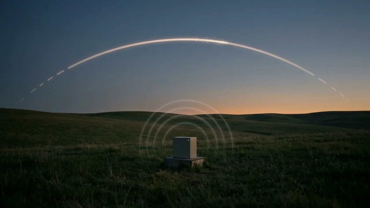
You may never see the person who threw a ball. Still, one glance at the ball in the air gives you a rough idea of where it came from. Its direction and the way it curves tell you about the path before and after that moment.
A counter-battery radar makes that guess with radio waves and calculation. It measures part of the path of an incoming shell or rocket and extends it both ways to find where the round came from and where it will land. A good starting point for the idea is projectile motion from a physics textbook. The textbook parabola leaves out air resistance, so the calculation in the real sky is more complicated.
What a radar reads from a shell
The U.S. Army calls this kind of equipment a counterfire target acquisition radar. It looks for rocket, artillery and mortar fire.
The basic idea is the same as for any radar. It sends short pulses of radio waves over an area and receives the small amount of energy that bounces back from objects. These echoes tell operators how far away an incoming projectile is, how high it is, how big it is and how fast it moves. How the round-trip time of a pulse gives distance is covered in Radar: measuring distance and motion with radio waves.
What sets a counter-battery radar apart is the next step. In an October 2012 Army article, the Army's product manager for radars said this radar predicts where an incoming round will hit by calculating its ballistic trajectory. Specially engineered computer algorithms help with this. Operators then work out where the hostile fire came from (the point of origin) and where it is expected to land (the estimated point of impact).
So the radar does not read a single dot. Positions and motion from many moments add up to one path, and that path points to both of its ends.
The parabola: finding both ends from part of the path
The basic shape of a shell's path comes from the textbook. When an object is thrown or launched into the air and only gravity accelerates it, the motion is called projectile motion. The path it follows is called its trajectory.
The motion gets easier when you split it in two. Sideways motion and up-and-down motion are independent, so you can treat them separately. If air resistance is small enough to ignore, nothing speeds up or slows down the sideways motion, and only gravity changes the vertical motion. Put the two together and the trajectory is a parabola.
A parabola does not bend at random. Its shape follows a fixed rule, so in this model, if you know one stretch of it exactly, you can draw the rest in both directions. The picture below shows the idea behind a counter-battery radar.
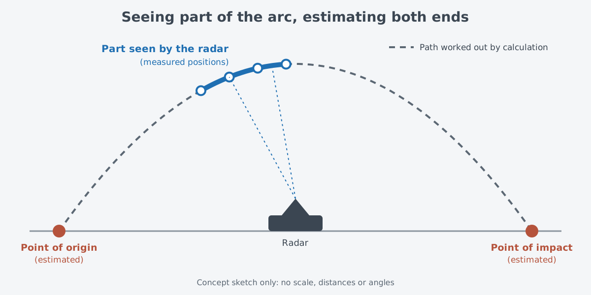
Think of the water arc in a fountain. Even if you see only one stretch of it, you can trace by eye which nozzle the water came from and roughly where it will fall. The real case is different. A radar measures positions with radio waves, not eyes, and the sky a shell flies through holds something the textbook left out.
The real sky is not the textbook
Textbook projectile motion leaves out the effects of air resistance from the start. After working through a fireworks example, the same section adds that in real life air resistance cannot be ignored entirely. To reach the same height, the fireworks shell would need a somewhat larger starting speed than the calculation gives.
Once air resistance comes in, the path of a round moves away from the textbook parabola. With air resistance, the launch angle that gives the longest range also becomes somewhat smaller. The textbook parabola is a starting point for thinking, and the path of a real round through real air is more complicated.
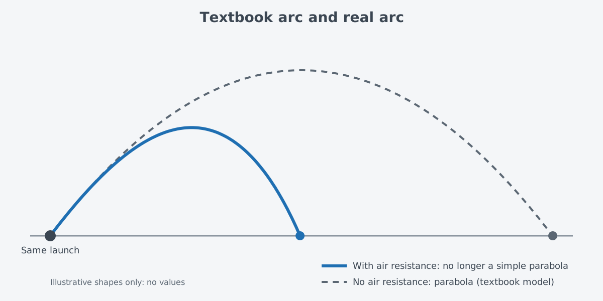
The trajectory calculation in a counter-battery radar uses specially engineered computer algorithms. What those algorithms compute, and how, does not appear in the public articles.
Generations of U.S. Army counterfire radar
The Army's earlier systems were the AN/TPQ-36 and AN/TPQ-37, known as Firefinder. The AN/TPQ-53, or Q-53, has taken their place. A 2022 Army article says that, like the systems before it, the Q-53 detects, classifies, tracks and locates enemy attacks.
The Q-53 grew out of a science and technology effort that tried to do several jobs with one radar: the Multi-Mission Radar Advanced Technology Objective (MMR ATO). The goal was one mobile radar for four jobs at once. It would watch the sky for air defense, direct air defense fire, locate hostile fire and support air traffic. An October 2012 article dates the start of this effort to 2002, while a November 2012 article describes five years of development starting in 2001.
After that, in 2006 an Army research center first demonstrated the concept behind the Q-53 as part of this effort. Then a quick reaction capability version first deployed in 2010. In February 2012 the program received its Milestone C decision, which approved low-rate initial production.
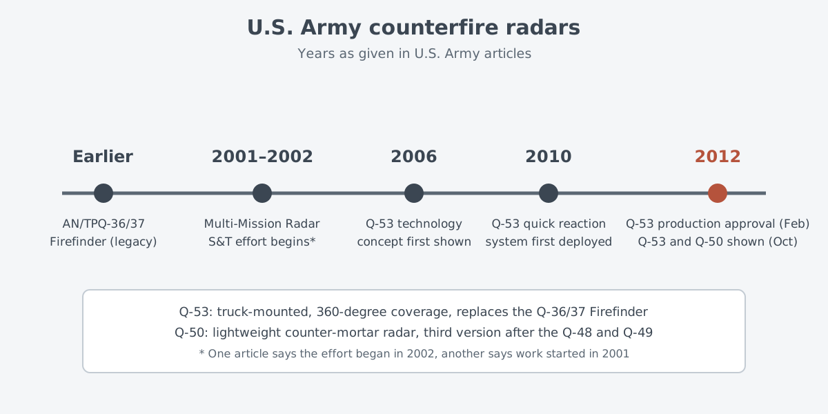
Both radars appeared together at a Pentagon display in October 2012, and fielding began at that time. The Army said these new-generation radars can protect or warn troops all the way around them, over 360 degrees, against incoming rocket, artillery and mortar fire. The Q-53 is truck-mounted, can be carried by a C-130 transport aircraft and is set up to detect threats from all 360 degrees. At the time, the product manager said software upgrades might one day let the Q-53 detect larger threats such as drones, cruise missiles, helicopters and fixed-wing aircraft.
The other radar is the AN/TPQ-50 Lightweight Counter Mortar Radar (LCMR), or Q-50. It is the third version after the Q-48 and Q-49, and it can ride on a HMMWV or stand on a tripod. Its cylinder-shaped radar steers its pulses electronically to cover 360 degrees. You can read how a radar changes direction without turning its antenna in Phased arrays and AESA radar.
The two radars were built to work as a team. The Q-50 was designed to work with the truck-mounted Q-53 and fill gaps that could appear in the Q-53's coverage.
Where this meets lasers: find it before you stop it
Counter-battery radar data is not only used to find where fire came from. According to the Army, both radars are set up to work with the Counter Rocket, Artillery and Mortar (C-RAM) ground systems used to guard forward operating bases. C-RAM combines a fire control radar with the rest of the system so that it can find incoming rounds, follow them and destroy them. The way such systems link sensors and weapons is covered in more detail in Fire-control systems.
The C-RAM job is also named as a possible role for laser weapons. A 2026 Congressional Research Service (CRS) primer on directed-energy weapons says ground forces might use high-energy lasers (HEL) for short-range air defense, counter-drone and C-RAM missions. In 2014, the Army said its demonstration systems had reached the point of shooting down mortar rounds and drones with high-energy lasers.
The point to notice is that detecting, tracking and destroying are tied into one system. Whatever handles the last step, the way C-RAM is built shows that the last step is linked to the detecting and tracking that come before it. How lasers, interceptor missiles and guns share defensive work continues in Lasers, interceptor missiles and guns: how they share the work.
What to read next
- Radar: measuring distance and motion with radio waves: the basic principle a counter-battery radar uses to measure distance and speed.
- Phased arrays and AESA radar: steering without moving: how radars like the Q-50 steer their beams electronically.
- Lasers, interceptor missiles and guns: how they share the work: how different tools split defensive jobs such as C-RAM.
- Self-propelled howitzers: what changes when a gun can move on its own: an article in the same land systems category.