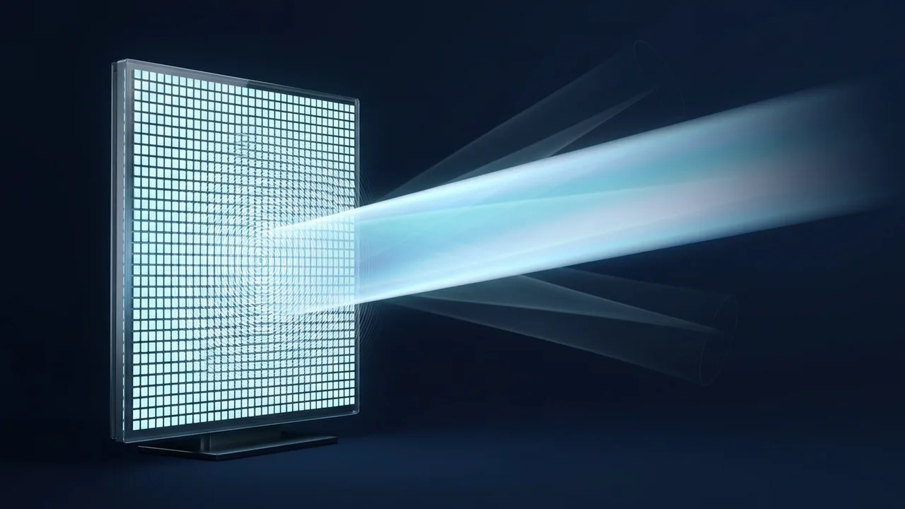
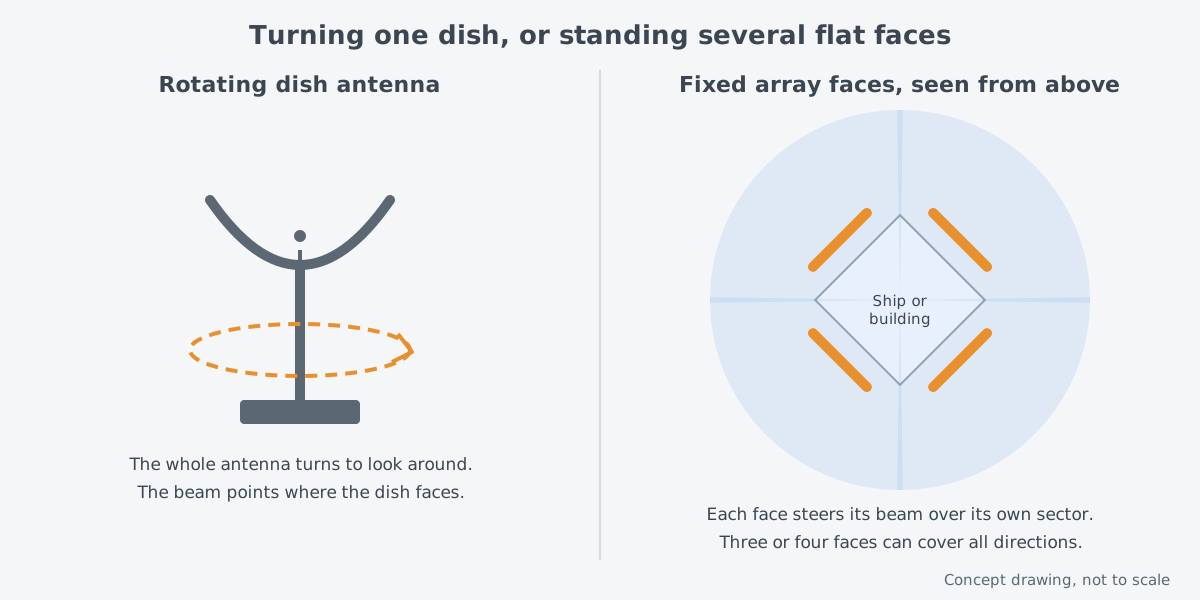
Photos of warships sometimes show large flat panels on the sides of the ship instead of a dish spinning on the mast. These panels are radar antennas too. They do not turn, yet their beam still looks this way and that.
How is that possible? Each panel holds a great many small antennas, and each one's signal rises and falls. If the point it has reached in that cycle, its phase, is staggered slightly from one antenna to the next, the waves gather strength in one direction only. An antenna that works this way is called a phased array.
So how can staggering the phase alone set a direction? And what separates a passive array (PESA) from an active one (AESA)?
Turning antennas and standing antennas
The airport surveillance radar of the U.S. Federal Aviation Administration (FAA) turns its tower-mounted antenna without stopping. The beam of such an antenna goes wherever the antenna faces, so looking somewhere else means moving the whole antenna. The basics of this kind of radar are covered in "Radar: measuring distance and motion with radio waves".
A new path opened in the 1950s. According to the technical history written at MIT Lincoln Laboratory, work then began on steering the beam by rapidly changing the phase of each element of an array antenna electronically. The idea was to use the speed and flexibility of electronics instead of much slower, less flexible mechanical steering.
The difference shows in use. A public Lincoln Laboratory lecture sums up that phased arrays give beam agility and flexibility and allow nearly simultaneous tracks over a wide field of view. There is no need to wait for a heavy antenna to swing back around.
The principle: many small antennas and phase
An array combines many antennas to strengthen the radiation and shape its pattern. In a phased array, the transmitted signal is divided into many paths called element channels, and each path has a phase shifter and an amplifier. When all the phase shifters are set correctly, the array forms one main beam pointing where it is wanted.
Phase tells where a wave is within one cycle of its rise and fall. Changing the phase is like starting a tiny bit later or earlier. The figure below shows what happens when each element sends a little later than its neighbor.
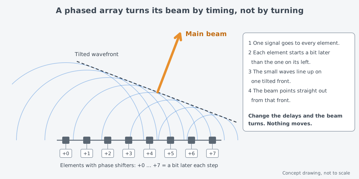
Picture dropping a row of pebbles into a pond, one after another from the left. The ripples from the first pebbles have spread farther, while those from the last ones are still small. So the fronts of the ripples line up along a tilted line, and the water moves out at right angles to that line.
The same thing happens with radio waves. When waves overlap, they grow stronger in some places and weaker in others; this is called interference. A phased array uses interference so that the waves add up only in the direction it wants.
The comparison stops there. A real radar does not drop a pebble once; it handles radio waves that oscillate without pause, and it sets the delay as a phase rather than as a time. The same elements also use the same principle when receiving, listening for signals that arrive from one direction.
Where passive (PESA) and active (AESA) arrays differ
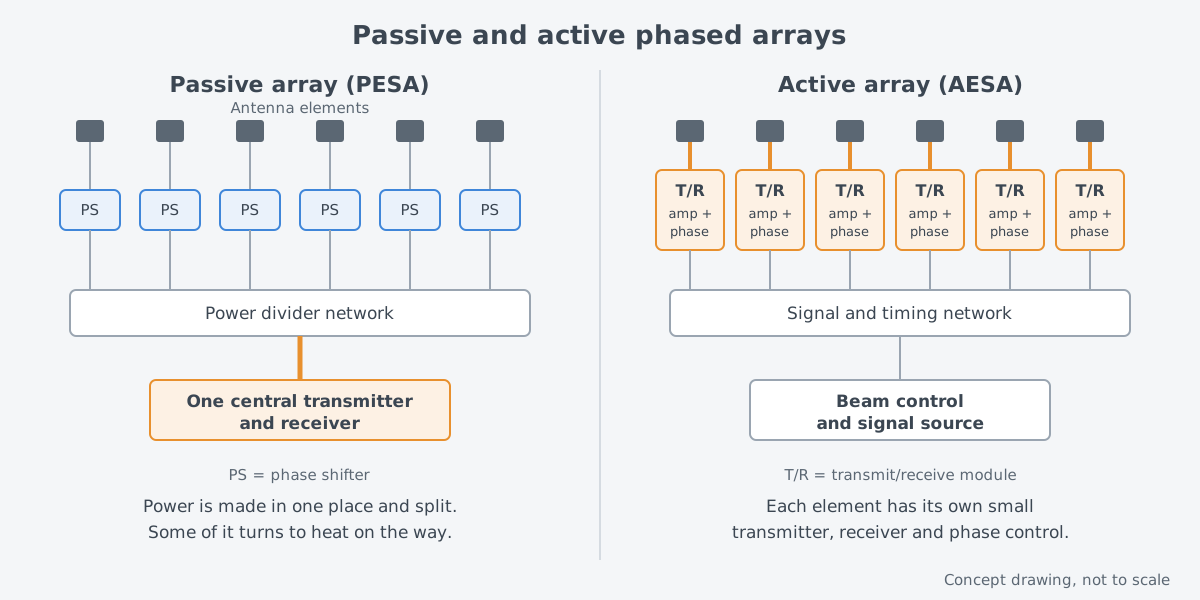
Both kinds steer the beam by adjusting the phase at each element. They part ways over where the radio power is produced. A Johns Hopkins Applied Physics Laboratory (APL) Technical Digest article describes the two layouts side by side.
In a passive electronically scanned array (PESA), one central transmitter, built from devices such as high-power microwave tubes, produces the power. That power is shared out to the elements through a high-power beamforming network, and a phase shifter at each element turns the beam toward the chosen angle. APL names the U.S. Navy's AN/SPY-1 radar as a leading example of a passive array.
The key part of an active electronically scanned array (AESA) is a small transmit/receive (T/R) module. Each radiating element has its own T/R module. The module boosts the power when sending, amplifies the signal with little added noise when receiving, and sets the phase that steers the beam. In effect, both sending and receiving have moved to the face of the antenna.
What the active design offers
The passive layout pays a price. Its transmit beamforming network loses a lot, so a large share of the power made by the transmitter turns into heat before it is ever sent out. The transmitter has to produce that much more power to make up for the loss.
An active array places its power amplifiers and low-noise amplifiers at the antenna face. According to APL, this sharply cuts the losses on transmit and receive and raises the radar's sensitivity for the same amount of power produced. Because the T/R modules control both amplitude and phase at each element, the radiation pattern is also easier to fit to the job at hand.
It also copes better with failures. The modules and their power supplies sit in many places. So an array can be designed to meet its performance requirements even if a few percent of its modules break down. That is unlike a layout where one large transmitter stopping stops everything.
These strengths helped the active design spread quickly. In 2001, APL wrote that nearly every high-performance radar then in development used an active array. Its examples included the THAAD and National Missile Defense radars and the fire-control radars of the F-22 and the Joint Strike Fighter.
The hard parts: cost, number of faces, coupling
First, cost. For the same power and antenna size, a phased array costs far more than a reflector antenna. Its parts cost more and its design takes longer. Lincoln Laboratory's 2000 review also wrote that phased-array radars still had to become cheaper.
Next, the number of faces. One flat array face covers only a set sector in front of it. So covering every direction, all 360°, may take three or four array faces.
Even within one face, there are conditions. The farther the beam is steered away from straight ahead of the face, the wider the beam becomes and the less it concentrates in one direction. In the pond picture, the more the ripple front is tilted, the less crisp the line becomes.
The elements also disturb each other. The effect of one element on its neighbors is called mutual coupling, and it can greatly complicate array design. In bad cases it can create scan blindness, a direction in which the array sends out no power at all. Meeting the needed scan coverage and bandwidth while avoiding blind spots and keeping unwanted side beams low is a major design challenge.
A short history: from 1940s arrays to solid-state modules
The idea of combining antennas is old. Early radio transmitters and early World War II radars already used several radiating elements to get the radiation shape they wanted. One early array radar was the U.S. Army's "bed spring" array. In the mid-1940s it became the first to bounce radar signals off the moon.
Those arrays could not steer their beams electronically, though. Describing early World War II array radars, the IEEE history wiki notes that they had no electronic beam steering, which is how modern radars search and track on their own.
Lincoln Laboratory began developing phased-array radar around 1958. The first use was satellite surveillance. After the Soviet Union put Sputnik I, the first artificial satellite, into orbit in 1957, the country took a strong interest in this work. Later, as ballistic missile defense drew more attention, the focus moved to flat, planar phased arrays.
The next turning point was solid-state electronics. The prospect of a phased array built entirely from solid-state parts arose in the late 1960s, and developers hoped such arrays would be smaller, lighter, cheaper and more reliable. Then came microwave chips made on gallium arsenide (GaAs), known as MMICs. They made T/R modules possible with the performance and reliability military radars need, at a cost that stays acceptable when many are built.
Lincoln Laboratory's 2000 review closed by saying that the electronic beam steering engineers had dreamed of in the 1950s was gradually coming true in many ground-based and airborne radars. Getting there took close to half a century.
An idea shared with lasers: many acting as one
At the core of a phased array is matching the phases of many small sources so they behave like one large source. The same idea appears on the laser weapon side. Among the ways of merging the light of several lasers, known as beam combining, the method that overlaps the light with matched phases is called coherent beam combining (CBC).
The two deal with different waves, though. According to NASA, radar instruments use long wavelengths on the scale of centimeters to meters. The light a laser handles has a far shorter wavelength.
So the devices that match the phases, and the difficulties, are different too. How lasers match the phase of light, and what makes it hard, continues in the beam combining article.
What to read next
- "Why beam combining is needed, and its three approaches": how several lasers are made to act as one.
- "Radar: measuring distance and motion with radio waves": the basic radar principles that came before phased arrays.
- "Fire-control systems: linking sensors and weapons": how a target found by radar is passed on to a weapon.