Look at a star through a telescope and what should be a single point shows up as a small, shifting blur. A laser beam gets distorted in a similar way as it passes through air, mirrors and lenses. To fix that, you first need to know where the light was distorted and by how much.
The device that does this job is a wavefront sensor (WFS). In our article on adaptive optics (AO), Adaptive optics: restoring a blurred beam, the sensor got only one paragraph. This article follows the best-known type, the Shack-Hartmann sensor.
The story starts with a plate that has a few holes drilled in it. How did that plate turn into an array of small lenses, and what do the spots behind those lenses tell us?
The wavefront: the leading edge of a light wave
Light is a wave. A surface that joins points at the same phase is called a wavefront. On water, it is the line you would draw along one crest. How waves overlap and spread is covered in Interference and diffraction: how light adds up and spreads.
Light from a very distant star arrives as a flat wavefront. As it passes through the atmosphere, that originally flat front becomes distorted, and the image a telescope forms turns blurry and unsteady.
A wavefront sensor's task is to give a signal accurate enough to estimate the shape of that wrinkled front. An adaptive optics system uses the sensor to measure the deviations, calculates a correction, and passes it to a deformable mirror (DM). The sensor is the eye of this loop.
The catch is that a wavefront cannot be seen directly. A camera records how bright light is, but a plain picture does not show which way the light was tilted when it arrived. A wavefront sensor contains an optical device that turns differences in phase into a signal that a detector can read.
A screen full of holes: the Hartmann test of 1900
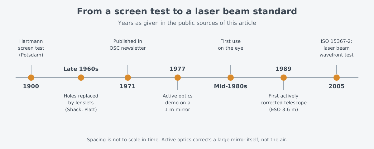
The Shack-Hartmann sensor goes back to a telescope test from 1900. Johannes Hartmann (1865–1936), a German astrophysicist, devised the test in the early 1900s, when he taught in Potsdam as a professor. The 80 cm refracting telescope he worked on in Potsdam could not take usable photographs because its optics were not good enough.
Hartmann drilled several holes into a plate and laid it over the front of the telescope. Only a set of thin ray bundles, one per hole, could then enter. He put photographic plates in front of and behind the focus and exposed them.
By joining matching spots on the two plates, he could see where each ray went near the focus. With good optics, every joined line meets the optical axis at one common point. Using this method, Hartmann found that the telescope's problem lay in its main lens.
One idea carries through to today's sensors. You divide the area the light passes through into small zones and check which way the light goes in each zone. The test then stayed almost unchanged for nearly 70 years.
Small lenses instead of holes: Shack and Platt
Change came from the United States during the Cold War. The U.S. Air Force wanted to photograph satellites from ground telescopes, but atmospheric turbulence distorted the images. The military asked Aden Meinel at the Optical Sciences Center (OSC) of the University of Arizona to take on the problem.
Meinel proposed splitting off part of the incoming light and running a Hartmann test on it to capture the air's aberrations at that instant. With those aberrations known, the recorded image could be cleaned up afterward. Roland Shack at the center got the job of finding out whether this would work.
A big obstacle soon became clear. A satellite sends only a little light down to a ground telescope, and most of it is needed to record the satellite image. Only a small share can go to the Hartmann screen, and the screen blocks every photon except those passing through its holes.
Shack solved this in two steps. First, he placed a small lens in each hole, so the light passing through was concentrated into a focal spot. Then he saw that if the lenses were made wide enough to touch at their edges, the plate could be dropped altogether. Every photon reaching the array would end up in some lens's focus, the most efficient arrangement for a device short of light.
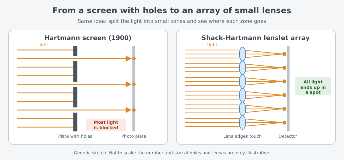
Ben Platt, then a graduate student at the center, was assigned to develop the lenslet array. According to a news article from the university's College of Optical Sciences, the two replaced the holes with a lenslet array in the late 1960s. The method then appeared as a short piece in the center's newsletter in March 1971. Later on, people came to call the device the Shack-Hartmann wavefront sensor.
The first sensor had an anticlimactic end. It went to an Air Force telescope that tracked satellites at Cloudcroft in New Mexico, but it never went into use, and its fate is unknown.
How far a spot moves tells the tilt
A Shack-Hartmann sensor covers the whole area where light comes in with small lenses laid out like a checkerboard. The small zone each lens covers is called a subaperture. Each lens gathers its light into one spot on a detector.
If the wavefront is flat, light enters each lens straight on, and each spot lands at its reference position right behind its lens. Where the wavefront is tilted, the light in that zone comes in at an angle, and the spot moves sideways by a matching amount. So the position of a spot shows the average tilt of the wavefront over that subaperture.
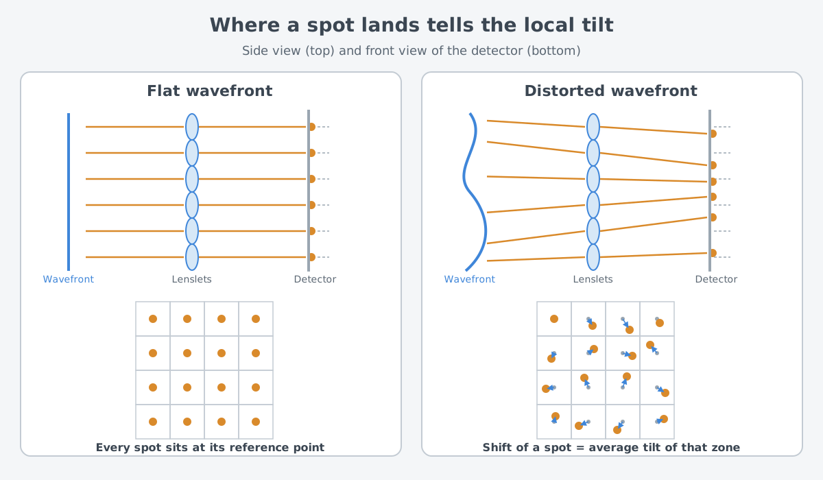
Picture a sloping yard divided into squares, with a ball placed in each square. By noting which way each ball rolls, you could map which parts of the yard are high and which are low. The real sensor differs in that spots of light shift instead of balls rolling, and each square reports only a tilt, not a height.
That is why the shape of the whole wavefront is rebuilt by calculation from those tilts. This step is called reconstruction.
ISO 15367-2:2005 is an international standard for measuring laser beam wavefronts with Hartmann or Shack-Hartmann sensors. It describes numerical methods for zonal and modal reconstruction of the two-dimensional wavefront, together with their uncertainty. The standard covers both pulsed and continuous beams.
The detector that records the spots matters too. A wavefront sensor usually includes a low-noise photon detector with high quantum efficiency. The wavefront hardly depends on wavelength. So astronomical AO often measures it in visible light, where detector technology is most mature, with CCD (charge-coupled device) sensors or APDs (avalanche photodiodes) doing the detection.
How detectors turn light into an electrical signal continues in Photodetectors: How a Photodiode Turns Light into a Signal.
Other wavefront sensors
The Shack-Hartmann is not the only kind. Astronomical AO currently uses three types of wavefront sensor: the pyramid, the Shack-Hartmann and the curvature sensor. All three work with broadband light, but they differ in measuring range and sensitivity.
A curvature sensor measures how light intensity is spread in two planes, one on each side of the focus. This corresponds to how much the wavefront bends, that is, its curvature. It looks at a different quantity from the Shack-Hartmann, which measures tilt.
A pyramid sensor uses a pyramid-shaped prism. When the prism is moved back and forth (modulated), it measures tilt much like a Shack-Hartmann. Without that motion, it works much like an interferometer, reading the phase itself rather than the tilt.
Sensitivity depends on what a sensor measures. A tilt sensor such as the Shack-Hartmann loses sensitivity toward the broad bends of the wavefront, the low spatial frequencies. A curvature sensor is more sensitive than a Shack-Hartmann to fine ripples at high spatial frequencies but is even weaker at the broad bends. The authors of an astronomical AO review pointed to its high sensitivity and flexibility and judged the pyramid sensor the strongest option for today's AO systems.
Stars, eyes, and laser beams
Astronomy was slow to adopt the sensor. During the first half of the 1970s, Shack gave lenslet arrays to astronomers who came to visit. Their value was only recognized when Ray Wilson of the European Southern Observatory (ESO) visited the center in 1976. Wilson had first conceived active optics in 1968: measuring the various aberrations of a large mirror and compensating for them actively.
After a second visit in 1977, Wilson took home a lenslet array from the first batch and showed active optics correction on a 1 m mirror with it. The CCD camera, which allowed the spot patterns to be captured and analyzed quickly, was another key. The University of Arizona history paper says the first astronomical telescope with active correction was ESO's 3.6 m telescope, whose first light came in March 1989. It adds that when the paper was written, the Shack-Hartmann method was by far the most used.
Active optics is not the same as adaptive optics, which corrects for the air. What active optics corrects is the aberration of the large mirror itself. The same kind of sensor served both jobs.
The sensor also moved into eye care. In the mid-1980s, Shack went to see Josef Bille of the University of Heidelberg, who became the first person to use the method on the eye. It first measured the shape of the cornea and later the aberrations of the whole eye.
The method played a central role in tailoring refractive surgery to each person. A University of Rochester group, using adaptive correction, was the first to resolve individual photoreceptors in a living eye.
Space telescopes deal with wavefronts too. The primary mirror of the James Webb Space Telescope is about 6.5 m across and made of 18 segments. A subsystem called wavefront sensing and control senses and corrects errors in its optics. Without it, the 18 segments could not act as one large mirror.
NASA notes that this work produced a spinoff technology used to diagnose eye conditions and map the eye precisely.
The laser side of the story has few records. The history paper says that in the early 1970s, secret U.S. programs were building high-energy lasers of the gas dynamic and chemical kinds. At those energies, heat bent the mirrors out of shape.
Correcting those mirrors adaptively required sensors to measure the distorted wavefront. It adds a caveat: a large part of the 1970s and 1980s work was classified, and some of it still is, so the full history is hard to tell.
Distorted wavefronts in laser beams are still being dealt with today. The National Ignition Facility (NIF) in the United States uses deformable mirrors to cancel wavefront errors in its laser beams.
Methods for measuring a laser beam's wavefront are set out in the ISO standard mentioned above. Knowing the wavefront makes it possible to find several wavefront parameters defined in the first part of that standard, ISO 15367-1. How official sources on laser weapons describe adaptive optics is collected in the adaptive optics article.
Limits and difficulties
The first limit is light. A wavefront can only be measured if there is light to measure, and astronomical AO is very often short of it. That makes good sensor sensitivity essential. Shack's lenslet array itself was born from a shortage of light.
Second, a Shack-Hartmann sensor needs spots to form. A star shines as a point, but the Sun is a broad, bright surface. Solar AO senses the wavefront from the low-contrast, ever-changing granulation pattern on the Sun's surface, and creates the spots a standard Shack-Hartmann sensor needs with a calculation called cross-correlation.
Third, each sensor sees some things well and others poorly. A tilt-measuring Shack-Hartmann loses sensitivity toward the broad bends. Because closed-loop AO deals only with small residual errors, sensitivity counts for more than measuring range.
Fourth, getting from measured values to mirror commands is not free. The simplest reconstruction method usually amplifies measurement noise a great deal. So real systems add steps that split the result into modes, filter it, and weight it.
The last limit is the record itself. Much of how wavefront sensors developed on the laser side remains classified. The paths that public sources let us follow are mostly astronomy, the eye, and test standards.
What changed between Hartmann's screen and Shack's lenslet array was a way to stop throwing light away. The idea of reading where each spot lands to learn the tilt of the wavefront has stayed the same ever since.
What to read next
| Article | Why it follows |
|---|---|
| Adaptive optics: restoring a blurred beam | The full loop in which the wavefront sensor works with the deformable mirror and the control calculation |
| Deformable Mirrors: Mirrors That Reshape Themselves to Fix a Beam | The part that takes the sensor's readings and actually flattens the wavefront |
| Photodetectors: How a Photodiode Turns Light into a Signal | How the detector behind the lenslet array records the spots |
| Beam quality: M², divergence and brightness | Another way to express how far a laser beam is from an ideal one |