Most mirrors are better the less they move. People who figure a telescope mirror work hard to make its face perfectly even. Yet one kind of mirror changes the shape of its face on purpose, over and over. It does so in tiny steps, and differently from spot to spot.
This is the deformable mirror (DM). It sits in adaptive optics (AO) telescopes that undo the shimmer of the air that blurs starlight, in giant laser facilities that clean up their beams, and inside space telescopes. Its name also shows up in official papers about laser weapons.
How does the face bend, and why does it need to? What kinds exist, and what is still hard? The larger system a deformable mirror belongs to is covered in Adaptive optics: restoring a blurred beam.
What a flat mirror cannot do
Light from a distant star first arrives as a flat wavefront. A wavefront is the leading edge of a light wave, the surface that joins points moving in step. When that edge passes through atmospheric turbulence, the path length differs from place to place, and the edge gets wrinkled.
A flat mirror sends those wrinkles straight back. Reflection changes the direction of the light, but it does not reshape the leading edge. Tilting the whole mirror can fix a beam that has shifted to one side as a whole. The wrinkles that differ from spot to spot remain.
Those leftover wrinkles are the deformable mirror's job. A review paper on astronomical adaptive optics defines its purpose as correcting the optical path differences made by the turbulent atmosphere. These are differences in the length of the path the light has traveled. The mirror pays back a difference in path with a difference in the height of its face.
A thin face and the actuators behind it
The layout is easy to sketch. There is a thin optical face, and behind it an array of actuators. When an actuator expands, the face above it is pushed out; when it contracts, the face is pulled back.
Where the leading part of a wrinkled wavefront lands, the face is pulled back so that part travels a little farther. Where a lagging part lands, the face is pushed forward to shorten its path. The reflected light comes out lined up again.
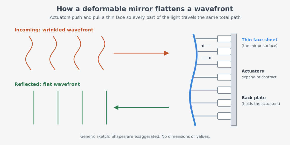
Picture a marching column thrown out of line on a bumpy road, and someone shifting each marcher's starting spot a little forward or back to straighten the line. In reality it is light, not people, the shifts are tiny, and the shape has to change without pause.
Four properties matter when choosing a mirror: stroke, response time, actuator spacing, and actuator count. Stroke is how far the face can be pushed and pulled, and response time is how fast it moves. Stroke and actuator count have to grow as the telescope aperture grows.
The mirror inside the feedback loop
A deformable mirror does not work alone. An adaptive optics system measures the deviation with a wavefront sensor (WFS), works out a suitable correction, and applies it to the deformable mirror. What the calculation sends the mirror is a set of voltages, one for each actuator.
The system has three elements. One is the deformable mirror, and another is a sensor that checks the aberration hundreds of times each second. The third is a control system that takes the measurements and tells the mirror where and how to move. Aberration means an optical effect that blurs or distorts an image.
In the common closed-loop setup, the mirror's place matters. The deformable mirror lies in the light path ahead of the wavefront sensor, so the sensor only sees the error left after the mirror has done its work. When the loop runs well, the leftover wavefront the sensor measures is close to zero.
Three families of deformable mirrors
A 2012 review paper sorts the deformable mirrors used in astronomical adaptive optics into three main technologies. In order of size they are adaptive secondaries, piezo mirrors and MEMS mirrors.
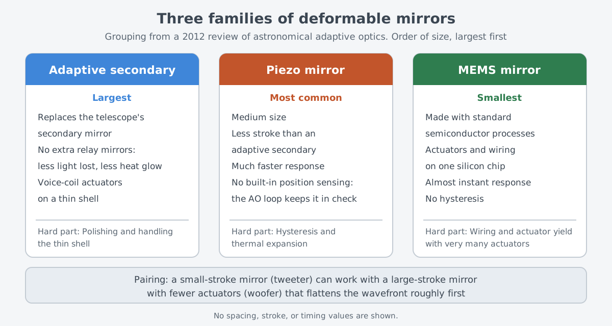
The largest is the adaptive secondary mirror. It replaces the telescope's fixed secondary mirror outright, so no extra mirrors have to be added just for correction. As a result it loses less light and gives off less heat radiation. Its actuators can be voice coils, each held in place by an internal control loop, and they are attached to a thin optical shell.
More common are medium-sized piezo mirrors, which have less stroke than adaptive secondaries but respond much faster. On the other hand, they usually have no way to sense their own position. They also suffer from thermal expansion and from hysteresis, where the same command can land in a slightly different place depending on earlier motion. So the adaptive optics loop has to keep watching them to deliver a precise, stable wavefront.
The smallest are MEMS (micro-electro-mechanical systems) mirrors. In the 2012 review they appear under the name MOEMS as a new alternative. They move by electrostatic or voice-coil action and are made with standard semiconductor chip processes. They are far smaller than other deformable mirrors, respond almost instantly, and show no hysteresis.
MEMS technology puts tiny actuators and their electrical connections on a single silicon chip. One branch of this family grew from a 1999 Small Business Innovation Research (SBIR) contract between a newly formed company and NASA's Jet Propulsion Laboratory (JPL). The aim of the contract was adaptive optics technology for space.
The families also pair up to cover each other's weak spots. Some MEMS mirrors and closely spaced piezo mirrors have only a small stroke. A system that uses them adds a second mirror with fewer actuators and a large stroke to flatten the wavefront roughly first. Like the bass and treble drivers in a speaker, the two are called the woofer and the tweeter.
From a 1953 idea to today's telescopes
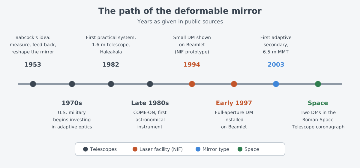
The idea came in 1953. Horace Babcock was an astronomer at the Mount Wilson and Palomar observatories in the United States. He wrote that the blur could be compensated by constantly measuring how rays from every part of the mirror deviate, then feeding that back to correct the mirror's figure locally. His sentence also held the hope of compensating for flaws in the optical surface itself, along with the shimmer of the air.
It took more than 30 years for technology to catch up. The U.S. military began investing in adaptive optics in the 1970s. In 1982 the first practical adaptive optics system went into service at the 1.6 m telescope atop Haleakala on Maui, Hawaii. The first astronomical instrument, COME-ON, was tested on a 1.52 m telescope in the late 1980s.
For the mirror itself, 2003 stands out. That year the first adaptive secondary was installed on the 6.5 m Multiple Mirror Telescope (MMT). When the 2012 review was written, another was in use at the Large Binocular Telescope (LBT). One more was being built for the Very Large Telescope (VLT) of the European Southern Observatory (ESO).
Around 2012 the largest deformable mirrors had some thousand actuators. The review projected that adaptive optics at visible wavelengths on a 40 m telescope would need a mirror with several tens of thousands of actuators. The bigger the telescope, the bigger the job the mirror has to do.
A similar-sounding technology is easy to mix up with this one. Active optics helps a telescope's main mirror keep its proper shape. Even so, ESO explains, turbulence distorts images at the best sites. Computer-controlled deformable mirrors correct that distortion in real time and make images nearly as sharp as pictures from space.
Beyond starlight: laser beams and space telescopes
The wrinkles a mirror fixes do not always come from the air. Engineers planning the U.S. National Ignition Facility (NIF) knew the beams would make four passes through the amplifiers. Along the way they would pick up wavefront aberrations from distortion in the amplifier glass and in other optical parts. The answer they found was the deformable mirror.
According to Lawrence Livermore National Laboratory (LLNL), each NIF deformable mirror sits where the main amplifier ends. An array of actuators bends its surface to offset wavefront errors in the laser beam. It corrects leftover heat distortion, flaws in optical materials, surfaces that are not quite flat, and amplifier distortion caused by heat from the flashlamps. Here the mirror smooths wrinkles made inside the laser itself, not by the air.
This mirror did not arrive overnight either. In 1994 a small deformable mirror was first demonstrated on Beamlet, NIF's prototype beamline, and in early 1997 a mirror covering the full beam aperture was installed on Beamlet. Behind it lay adaptive optics experience from LLNL's Atomic Vapor Laser Isotope Separation program.
Space telescopes use deformable mirrors even though there is no air. The coronagraph on NASA's Nancy Grace Roman Space Telescope is built to block the glare of a distant star so the planets around it can be imaged directly. Two deformable mirrors inside it are key parts, with thousands of actuators moving like pistons to offset small flaws in the telescope's optics and changes in them.
NASA says the changes on these mirror surfaces are precise enough to correct errors narrower than a single strand of DNA. A 2010 NASA Spinoff article also notes that in space, adaptive optics corrects telescope distortions caused by temperature, launch impact, and the absence of gravity.
There are uses on the ground as well. Laser communication through the air is limited in speed and accuracy by turbulence and other interference. When that article was written, scientists were finding that correcting the distortion with adaptive optics allows faster data rates at greater distances. Vision researchers were testing MEMS mirrors to remove blur caused by eye tissue and see the retina more clearly.
Official papers on laser weapons mention the mirror too. A U.S. Navy budget document quoted in a Congressional Research Service (CRS) report described a project to build up the industrial base that makes parts for laser weapon beam directors. The project included improving quality and cutting production times for fast steering mirrors (FSM) and deformable mirrors.
The same document called the two mirrors "highly critical, difficult to manufacture components." According to the FY2025 budget document, the project's work wrapped up in the third quarter of FY2025. What is public is this story of production and supply; these documents do not say how the mirrors are used inside a weapon.
Limits and difficulties
The first limit is the number of actuators. A mirror with a finite number of actuators cannot fully follow wavefront errors that are wrinkled very finely, in other words errors at high spatial frequencies. The error left over is called the fitting error. It scatters light far from the center of the image, and it harms many kinds of observation more than low-frequency errors do.
Each family has its own difficulties. For adaptive secondaries, polishing and handling the large, thin shell is a major challenge. Piezo mirrors need constant watching by the loop because of hysteresis and thermal expansion. For MEMS mirrors, once the actuator count gets very large, routing the wiring on the chip and the actuator yield become technical challenges.
Getting both stroke and fine spacing from one mirror is also hard. Some finely spaced small mirrors have too little stroke to handle large wrinkles alone. That is why two mirrors have to be used together, as a woofer and a tweeter.
Still, some see the future of the field riding on the mirror. The authors of the 2012 review judged that adaptive optics was conceptually mature. In their view, the largest progress would come mainly from deformable mirrors with densely packed actuators and from fast, powerful real-time computers.
What to read next
| Article | Why it follows |
|---|---|
| Adaptive optics: restoring a blurred beam | The larger loop the deformable mirror runs in, with the wavefront sensor and guide stars |
| Fast steering mirrors: small, quick mirrors that cancel shake | A mirror that steadies the direction of the whole beam rather than its shape |
| Wavefront sensors: measuring distortion with a Shack-Hartmann sensor | The part that tells the deformable mirror what to fix |