Walk into a field after rain and your feet sink with every step. Yet a main battle tank, far heavier than any person, rolls across that kind of ground. How can something so much heavier sink less?
There is more than one answer. Tracks lower the pressure on the ground, suspension carries the hull over bumps, and engineers build models that try to predict how soil and vehicle will behave together. This article follows that story from a track patent in 1904 to a NATO demonstration in 2018.
Same weight, different area
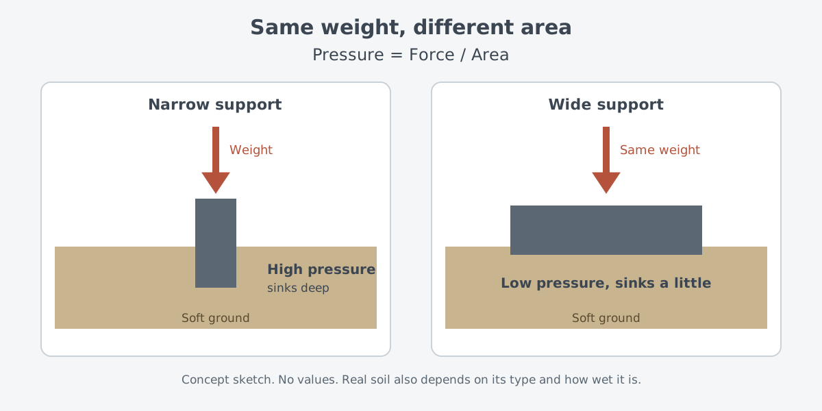
Pressure is a force divided by the area it acts on. A physics textbook puts it in one line.
P = F / A
P is pressure, F is force, and A is the area at right angles to the force. The same force can do very different things depending on that area. A poke with a finger hardly hurts, but the same force on a spot as small as a needle tip breaks the skin.
Ground works the same way. Keep the weight of a vehicle fixed and double the area touching the ground, and the formula says the pressure on the ground drops by half. It is the reason a plank laid over mud keeps your feet from sinking as deep.
Real soil is much less simple than mud under a plank. How well it holds up a vehicle depends on the type of soil and how wet it is. Pressure alone cannot tell you whether a vehicle will get through. The story of measuring soil and building prediction models comes later in this article.
Tracks: a road the vehicle lays for itself
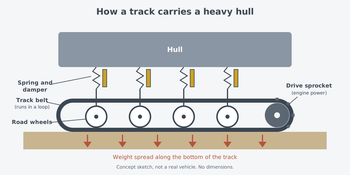
A track is a belt that wraps around a set of wheels and runs in a loop. As the vehicle moves, the bottom of the belt lies flat on the ground and the wheels roll along it. In a way, the vehicle carries its own road.
Where does the driving force come in? On the British Vickers Mark E tank of 1928, power from an engine at the rear went through a gearbox to toothed wheels called sprockets at the front. The sprockets turn the track, and the road wheels under the hull roll along the moving track.
Wide tracks tie straight back to the pressure formula. The Tank Museum at Bovington, England, says the wide tracks of the German Panther of the Second World War spread the tank's weight on soft ground. Instead of a few wheels touching the ground on small patches, the long, wide underside of the belt takes the weight and passes it to the ground.
Suspension: springs and dampers
Good contact with the ground is only part of the job. Ground is not flat, and the wheels move up and down over every rock and rut. The parts between the wheels and the hull that take up this motion are called the suspension.
The textbook uses a car to explain it. When a person gets in, the car settles a little on its suspension, and the springs push back with a force equal to the added weight. That push is called a restoring force.
With springs alone, the car would bounce up and down every time someone climbed in. A shock absorber is the part that calms that bouncing through friction. A car that keeps bouncing is a sign of worn shock absorbers.
When the goal is to get rid of shaking, you want the body to settle back to its resting position as fast as it can. There are still limits. Speed bumps and gravel roads can set a car shaking hard even with well-made shock absorbers, and the textbook gives this as an example of resonance.
A tank's suspension does the same two jobs in the end. It holds up a heavy hull, and it tames the shaking that the ground sends up. How it does that has changed from one era to the next.
From tractor to tank
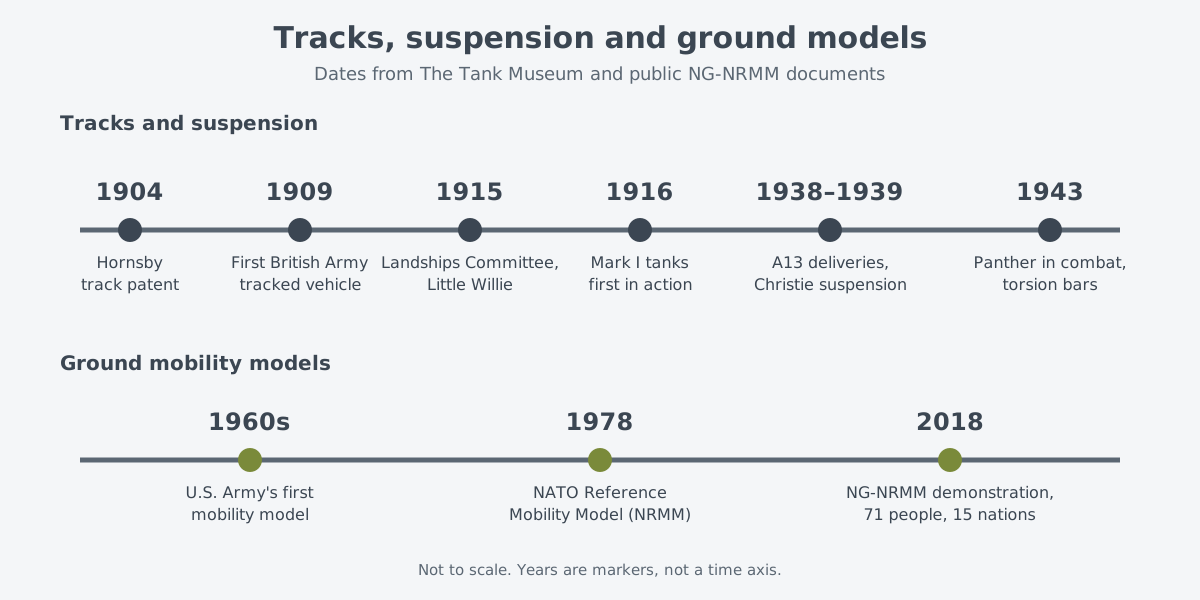
Tracks came before tanks. In 1904 David Roberts of the British firm Richard Hornsby & Sons patented a new crawler track, and the War Office tested a vehicle fitted with it in 1907. Ordered for military use in 1909, that vehicle became the British Army's first tracked vehicle. Soldiers who watched it move are said to have coined the word "caterpillar."
That tractor did not lead straight to the tank. The Tank Museum says the Hornsby tractor played almost no part in how the tank developed. In its account, the tank grew in 1915 out of a different line, by way of the Pedrail system of Diplock and a Chicago tractor company named Bullock.
In 1915 Winston Churchill, then First Lord of the Admiralty, set up the Landships Committee to deal with the problems that trench warfare posed. William Foster & Co., a farm machinery firm in Lincoln, took on the prototype, and William Tritton and Walter Wilson fitted it with tracks that worked. The result, Little Willie, is counted as the world's first working tank.
Little Willie had a problem. Its tall, boxy shape meant it could not cross a 3 m gap, the usual width of a German trench. By the time it was finished, Tritton and Wilson already had another idea: a machine whose tracks wrapped around the entire hull.
That idea became the rhomboid tank called Mother. Its long shape, sticking out at the front and back, let it cross an 8 ft trench. Wilson is widely credited with the track design for Little Willie and for Mother, whose tracks ran around the whole vehicle.
Tanks went into combat for the first time on 15 September 1916, at the Battle of Flers-Courcelette. Top speed at the time was around 4 mph on roads and perhaps half that across country. On the night move to their start points, many tanks failed to get there, mostly because they ditched or broke down. Fitting tracks had not solved the problem of the ground.
Suspension changed too. The British A13 cruiser tank was the first British tank with Christie suspension. J. Walter Christie, an American motor racing driver, built very fast tanks known for big wheels and powerful springs.
The museum's own A13 is one of 65 handed over from December 1938 to November 1939.
The German Panther, first in combat at Kursk in 1943, had torsion bars and, on each side, 18 road wheels set so that they overlapped. The museum calls this suspension more complex than the one on the Soviet T-34.
Measuring soil, predicting the way
Can anyone tell in advance which ground a vehicle can cross? The U.S. Army built its first mobility model in the 1960s. A 2022 briefing by the chief scientist of the Army's Ground Vehicle Systems Center (GVSC) lists its uses as operational analysis, acquisition and design.
The inputs are vehicle data, terrain maps, and scenario and weather data. The terrain maps hold soil, the shape of the land, vegetation, and roads and obstacles. What stands out is that the model takes in the ground, not just the vehicle.
The NATO Reference Mobility Model (NRMM) followed in 1978. NRMM is a set of empirical models built from tests in the late 1960s and 1970s, and it leans heavily on soil measured on site. In the briefing, the names cone penetrometer and vehicle cone index also sit on the empirical side of the chart.
The next step is the Next-Generation NRMM (NG-NRMM), which works from physics. A NATO Science and Technology Organization research group, AVT-248, brought together 71 people from 15 nations. After four years of work, they showed the results on 25–27 September 2018 at Michigan Technological University's Keweenaw Research Center. They paid special attention to how vehicles move over soft or borderline ground.
What is still hard
NRMM has been in use a long time, and its limits are clear. A technical memo on the demonstration notes that many of its off-road mobility calculations come from observation, so stretching them beyond the test conditions can give wrong answers.
Its handling of suspension has limits as well. For obstacle crossing, NRMM fits every tracked vehicle suspension into a single form called an "equivalent walking beam." For that reason, the memo judges that NRMM should not be used for vehicles with technology very different from today's, such as active suspension.
Soil is harder still. In the soft soil tests at the 2018 demonstration, NRMM predicted drawbar pull, the force a vehicle can pull with, well only in wet, fine-grained soil. Work listed for the future includes understanding and matching very different kinds of data, such as cone index, bevameter readings, remotely sensed terrain and moisture.
Pressure started out as a one-line formula. Predicting how a heavy vehicle will move over real soil, though, is still an open research problem.
What to read next
- Main battle tanks: is it all about the gun?: the balance of firepower, protection and mobility that rides on the tracks.
- Infantry fighting vehicles and APCs: how they differ from tanks: how tracked vehicles that look alike end up with different jobs.
- Tank Gun Stabilization: Why the Gun Stays Steady on the Move: how the gun deals with the shaking that the suspension does not absorb.
- Gimbals, pointing and tracking: holding the beam on one spot: the same kind of problem, holding a laser beam on one spot from a shaking mount.