Fold the tail of a paper airplane a little and it flies off in a new direction. Real airplanes work in a similar way: control surfaces on the tail and wings push on the air to change course. But what turns the aircraft when the air is no longer flowing smoothly over the wings?
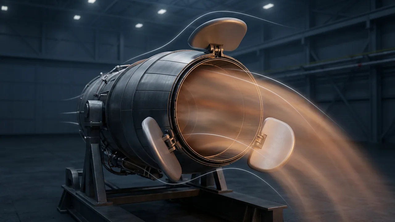
One answer is to bend the exhaust coming out of the engine. This is called thrust vectoring. This article uses NASA's public education pages to explain how thrust and rotation work, then follows what NASA learned from two test aircraft and what it cost.
Thrust is a force with a direction
Thrust is the force that pushes an aircraft forward through the air. An engine throws gas out the back at high speed and gets a push forward in return. That is why thrust acts opposite to the gas it accelerates.
A force has a size and a direction. Thrust has both, so it is a vector. Change the direction the exhaust leaves the engine, and the direction of the push changes with it.
The NASA fact sheet on the X-31 test aircraft explains thrust vectoring as "directing engine exhaust flow." The name sounds technical, but that short phrase covers what it does.
Miss the center of gravity and the aircraft turns
The center of gravity marks the average position of an object's weight. Airplanes and rockets in flight both rotate about this point. Any motion of the aircraft can be split into two parts: where the center of gravity goes, and how the aircraft turns around it.
There are three axes to turn about. Pitch moves the nose up or down, yaw moves it from side to side, and roll moves the wing tips up and down. A normal airplane uses the elevators for pitch, the rudder for yaw and the ailerons for roll.
The air forces from these control surfaces act some distance away from the center of gravity. Because of that offset, they create a torque around that point. The torque is what turns the aircraft. In aviation the same quantity is also called a moment.
Thrust follows the same rule. If the thrust line runs straight through the center of gravity, the vehicle is pushed forward without turning. If a bent nozzle makes the thrust line pass beside that point, the push creates a torque and the nose swings. In NASA's rocket drawing, bending the nozzle to the left turns the nose to the left.
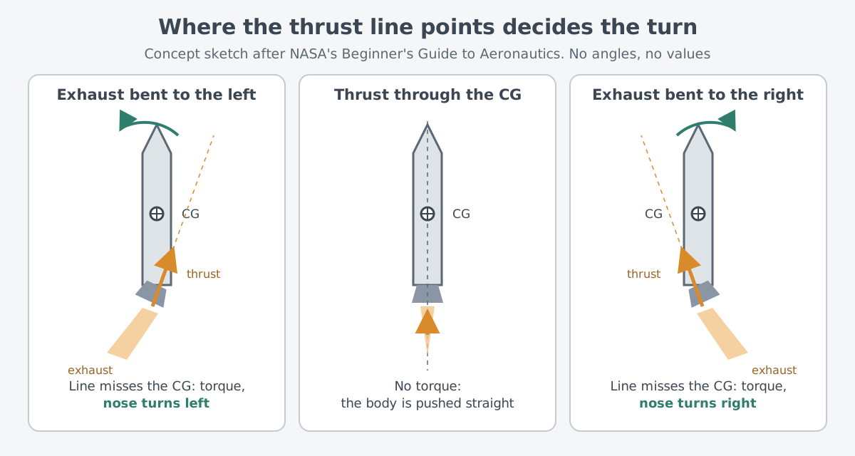
Think of a book lying on a desk. Push it in the middle and it slides straight. Push one end and it turns as it slides. A real aircraft is different: it moves through air instead of sliding against a desk, and it can turn about three axes, not just one.
Several ways to bend the exhaust
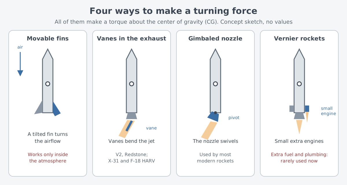
There are several ways to turn a vehicle. Each one creates a turning force around the center of gravity. Some air-to-air missiles, like the earliest rockets, steer with movable fins that work much as an airplane's elevators do. Because these fins push on air, they only work inside the atmosphere.
Where there is no air, another method is needed. Later rockets built to leave the atmosphere, such as the V2 and Redstone, placed small vanes in the exhaust to bend the jet. Older rockets such as the Atlas missile added small vernier rockets near the base of the main engine. The extra fuel and plumbing added weight, so vernier rockets are rarely used now.
Most modern rockets swivel the nozzle itself. This method, used on the Saturn V and the Space Shuttle, is called gimbaled thrust. Swinging the nozzle from side to side changes where the thrust points compared with the center of gravity, and that produces a torque.
The word gimbal also comes up often in laser weapons. There, a gimbal is a mount that holds optics and turns them about two axes. Gimbals, pointing and tracking shows how a mount with the same name keeps a beam on one spot.
Where wings lose their grip: angle of attack and stall
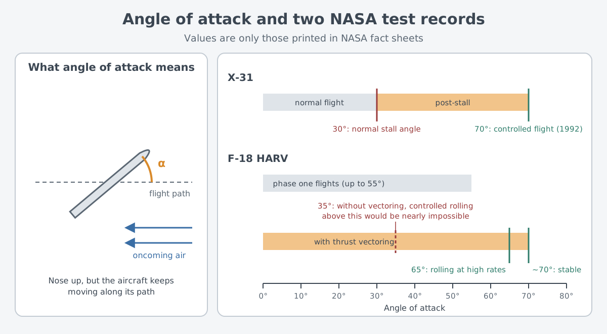
Angle of attack (AoA) is the angle of the wings relative to the oncoming wind. In hard maneuvers, pilots sometimes hold a large angle of attack: the nose is raised, yet the aircraft keeps traveling the way it was going. The X-31 fact sheet warns that such flight can end in a loss of control, costing the aircraft, the pilot, or both.
If the angle of attack grows too large, the airflow separates from the wing surface. Lift drops and drag rises, and this condition is called a stall. In a stall, the normal control surfaces on the wings and tail can no longer handle the aircraft well.
This is where thrust vectoring proved useful. On the X-31, thrust vectoring made up for the control lost through the normal surfaces during a stall. Flight past the usual stall angle is called post-stall flight, and on the X-31 that stall angle was 30°.
NASA's two test aircraft: the X-31 and the F-18 HARV
Two X-31 Enhanced Fighter Maneuverability (EFM) demonstrators flew. Based at NASA's Dryden Flight Research Center and at Palmdale, California, they gathered data that might feed into the design of future highly maneuverable fighters. The program closed in June 1995.
Three paddles beside the engine nozzle bent the exhaust to control pitch and yaw. The paddles were made of graphite epoxy and could withstand temperatures up to 1,500 degrees Celsius for long periods.
On November 6, 1992, the second X-31 flew under control at a 70° angle of attack. On the same day it also flew a controlled roll about its direction of travel at that angle. That is far past its 30° stall angle, with the aircraft still under control.
The F-18 HARV was an F-18 Hornet fighter rebuilt as a High Angle-of-Attack Research Vehicle. NASA Dryden flew it from April 1987 to September 1996 in three phases, for a total of 385 research flights. In the first phase, with no changes to the outside of the aircraft, flights reached angles of attack up to 55°.
In the second phase, the HARV received three paddle-like vanes around the exhaust of each engine. The vanes were made of Inconel, a heat-resistant nickel alloy. They supplied pitch and yaw forces when the aerodynamic controls could not be used or did not work well enough. The flight control laws blended aerodynamic control and vectored thrust, so after the system was switched on, the pilot used the normal cockpit controls.
As a result, the HARV flew steadily at about 70° angle of attack and rolled at high rates at 65°. The fact sheet judges that controlled rolling above 35° would have been nearly impossible without vectoring.
The work left more than records. According to the HARV fact sheet, lessons from high-angle-of-attack research show up in part in the F-22. They also appear in the Joint Strike Fighter (JSF) prototypes. Thrust vectoring research continued at Dryden with the X-31 and the F-15 ACTIVE research aircraft.
What it cost
On the test aircraft, thrust vectoring did not come free. The HARV's vectoring hardware made the aircraft 2,200 pounds heavier. Engine performance below the speed of sound stayed largely the same, but the aircraft could no longer fly faster than sound. That last penalty applied only to this experimental project.
The X-31 also ran into limits. At a 58° angle of attack, the aircraft unexpectedly departed from controlled flight. Engineers traced this to very large side-to-side asymmetries that pushed the nose harder than the available thrust vector controls could correct.
The team added thin strips called strakes to the nose and blunted the nose tip slightly to reduce this asymmetry. The 70° record came after these changes, so thrust vectoring alone did not solve every problem.
The test pilots did not support giving up other important fighter qualities just to gain the X-31's maneuvering abilities. At the same time, the X-31 stayed fully controllable in the post-stall region, which greatly improved flight safety.
In 1994 the X-31 was also used to mimic a fighter with a smaller tail. Software installed in the X-31 explored whether thrust vectoring could keep a tailless aircraft stable at supersonic speed. The test showed that tailless and reduced-tail fighters were feasible. NASA's summary is that if this ability had been part of the design from the start, its benefits could have outweighed the added complexity.
On these two test aircraft, the lessons were the weight of add-on hardware and the complexity of control. A third was that designing it in from the start beats adding it later.
What to read next
- VTOL and STOVL: flying from short runways: the next article in the military aircraft category on how engines and flight connect.
- Ramjets and scramjets: engines without fans: how the engines that make thrust work.
- Air-to-air missiles: what the missile sees: a closer look at how the air-to-air missiles mentioned here see their targets.
- Gimbals, pointing and tracking: holding the beam on one spot: what a mount with the same name does on the laser side.