A laser diode is a semiconductor chip smaller than a fingernail. A NASA test guideline for laser diodes describes mounting a group of these chips on a heat sink and resting that heat sink on a thin plate. Send current into the plate, and one face turns cold while the other turns hot. This is a thermoelectric cooler (TEC).
Why put something like a tiny refrigerator under a part that makes light? A laser diode changes when its temperature changes, even a little: its wavelength, the current at which it starts lasing, and even its lifetime. This article looks at what temperature does to a laser and how a TEC moves heat with electricity. It then covers how a feedback loop holds one temperature, and where this small plate stops being useful.
A few degrees, a fraction of a nanometer
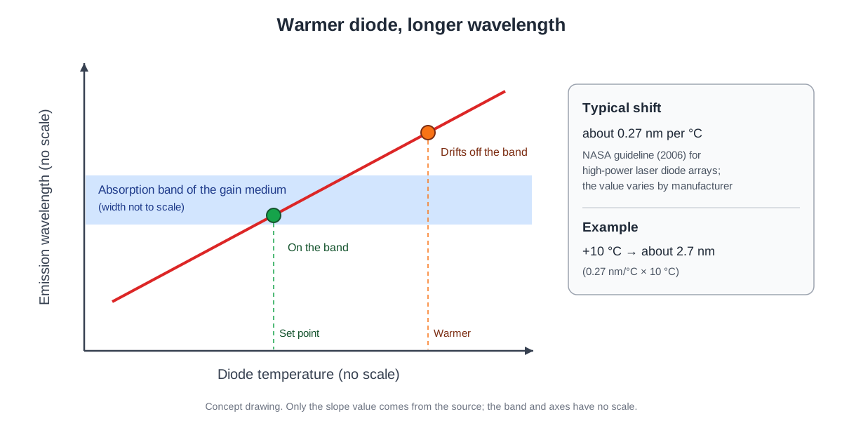
When a laser diode warms up, the wavelength of its light grows longer. A 2006 guideline on high-power laser diode arrays from NASA's Goddard Space Flight Center uses a typical shift of about 0.27 nm per degree Celsius. It adds a caution: the figure is not fixed and changes from one diode maker to another.
0.27 nm looks tiny. Yet at that typical value, a rise of just 10 °C moves the wavelength by 2.7 nm. Why do a few nanometers matter?
A pump diode is the light source that shines into the gain medium of a solid-state or fiber laser. Diode arrays have a much narrower spectrum than a flashlamp, so they can be tuned straight into an absorption line that the gain medium takes in well. The pump light is then absorbed better, and heating effects are smaller. If the matched wavelength drifts with temperature, that advantage shrinks.
Wavelength is not the only thing that moves. A laser diode turns from LED-like light to coherent laser light only once its current passes the threshold current. Wavelength Electronics, a company that makes diode drive equipment, explains that this threshold depends on the style of diode and on the temperature of its case.
Lifetime is tied to temperature too. The NASA guideline states that lowering temperature and electrical stress during operation greatly reduces aging in the semiconductor. With the same current going in, a diode at a different temperature behaves almost like a different laser.
A plate that pumps heat with electricity
Inside a TEC, n-type and p-type semiconductor pieces stand side by side in turn. Electrically they form one chain (in series), while thermally they sit side by side (in parallel), sandwiched between two ceramic plates. The ceramic blocks electricity but passes heat toward the heat sink.
Apply a voltage, and the current moves electrons from one face to the other, which sets up a temperature difference between the faces. This is the Peltier effect. One face loses heat and turns cold; the other face takes that heat and turns hot.
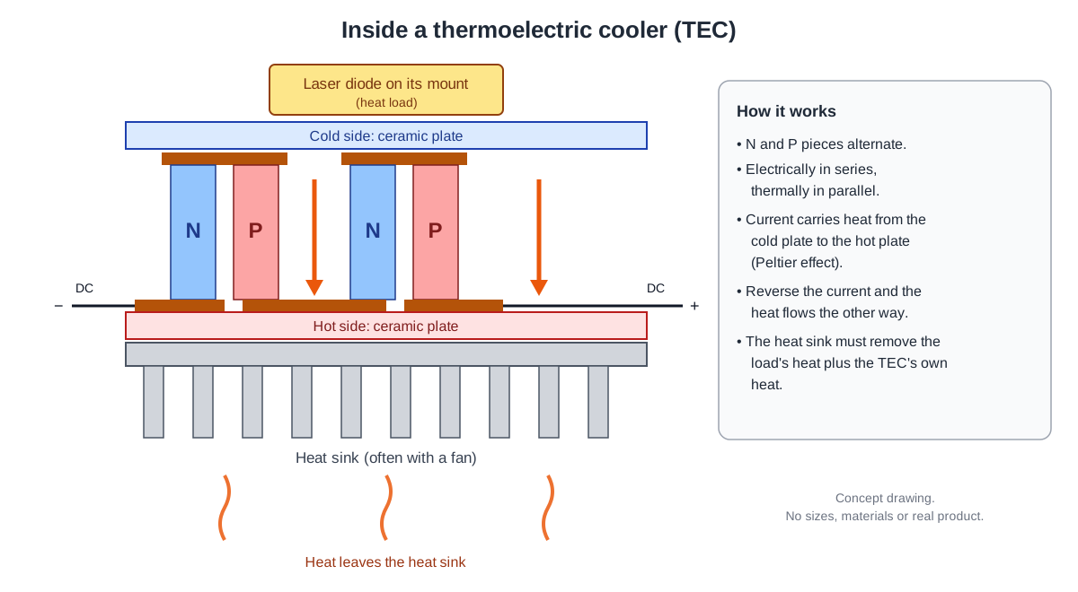
Reverse the current, and the heat flows the other way. The same plate can cool or heat, so for a controller that drives a TEC, the direction of the current matters as much as its size. People also call it a heat pump or a Peltier cooler, and stacking plates in several stages gives a larger temperature difference.
A refrigerator is a useful picture here. It also moves heat out of its inside and dumps it at the back.
The real difference is in how. A refrigerator runs a refrigerant through a compressor. The core of a TEC has no moving parts; electric charge flowing through the semiconductor carries the heat.
The hot side works harder
Wavelength Electronics puts the efficiency of thermoelectric devices at about 10% and notes that the electric power fed to the device also ends up as heat that must be removed. So the heat sink on the hot side has to get rid of the heat pumped from the laser plus the heat the TEC makes itself. That is why the hot side carries far more heat than the cold side.
A heat sink that is too small causes trouble. As the temperature rises, the sensor reports it, and the controller pushes more current to cool harder. The extra current piles more heat onto a heat sink that is already struggling, and the temperature climbs again.
This loop is known as thermal runaway. Too much current is also a way to damage the TEC itself, so temperature controllers include a limit that keeps the current from passing a set maximum.
The NASA guideline's test setup shows the same thinking. For measurements at a controlled temperature, the laser diode array is mounted on a heat sink that rests on a Peltier TEC. The cooler must be able to remove the array's heat and hold it steady, even when the test runs at its coldest operating point.
Measure, compare, correct
The purpose of temperature control is to hold a device at one temperature. The first step is to measure. The usual sensor is a thermistor, a resistor whose resistance changes with temperature. Most are the negative temperature coefficient (NTC) type, whose resistance falls as the temperature rises.
Next comes the comparison. The controller compares the measured temperature with the setpoint chosen by the user and calls the difference the error. A control scheme called PID turns that error into the current sent to the TEC. If the laser is too warm, current flows the cooling way; if it is too cool, current flows the heating way.
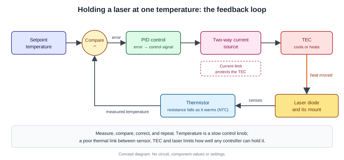
This loop follows the same basic idea that laser textbooks give for active stabilization. The output is compared with a reference to get an error, and a control knob is turned to shrink that error, in a closed loop. Keller's Ultrafast Lasers lists laser temperature among the control knobs as "very slow" and the injection current of diode-pumped lasers as fast. Temperature is a knob for holding steady over time, not one to turn in an instant.
How steady can it get? Wavelength Electronics says that sensors such as thermistors commonly reach stabilities of 0.01–0.001 °C, while less precise thermocouples reach about 1 °C. Still, if the sensor, the TEC and the laser are poorly linked by heat, even the best controller cannot help.
The sensor needs care too. If too much current runs through a thermistor, it heats itself and reports a temperature higher than the real one. The device that measures temperature ends up changing it.
From an 1834 watchmaker to semiconductor coolers
It began with a compass. In 1821 (1821–1823 in some sources), Thomas Johann Seebeck studied a loop made of two different metals. When its two junctions were at different temperatures, a nearby compass magnet turned. The temperature difference produced a voltage that drove a current around the closed loop, and the name for it today is the Seebeck effect.
In 1834, Jean Charles Athanase Peltier, a French watchmaker who also worked in physics part time, found the reverse effect. Current sent through the point where two different metals met could warm that point or chill it. In 1838, Lenz showed that the direction of the current decides what happens. One way, the current draws heat out of the junction and freezes water; reverse it, and the ice melts.
Useful coolers came with semiconductors. In 1949, Abram Ioffe built the modern theory of thermoelectricity around the idea of a figure of merit. The materials with a high figure of merit were usually heavily doped semiconductors.
In the 1950s, researchers showed cooling from room temperature down below 0 °C. One of the first to do it was H. Julian Goldsmid, who used bismuth telluride (Bi₂Te₃) elements in 1954.
A small but stable industry then grew up making Bi₂Te₃-based Peltier coolers, and they now go into products from optoelectronics to small refrigerators and seat heating and cooling. Other methods are more efficient, but reliability and simplicity keep this niche alive.
Semiconductor lasers were also born in the cold. In 1962, three U.S. research centers raced to build the first semiconductor laser. A GE photo from that time shows one as a tiny crystal hanging inside a glass vessel of liquid nitrogen.
According to the Nobel Foundation's background paper for the 2000 physics prize, heterostructures were what lowered the threshold current enough for continuous operation without extra cooling. Continuous operation at room temperature was reported in 1970. Today, the job of a TEC under a laser diode is less about making it very cold and more about holding it at a chosen temperature.
Thermoelectric cooling beyond lasers
Devices that measure light care about temperature as well. Cooling a photomultiplier tube reduces its dark current and the noise pulses that come with it, which improves the signal-to-noise ratio. Hamamatsu's handbook lists air, water and thermoelectric cooling as common methods and notes that water and thermoelectric cooling can go below the surrounding temperature.
A Peltier element has no moving parts that cause vibration or noise. That suits instruments that measure very faint light. The same company describes thermoelectrically cooled silicon photodiodes as giving a much better signal-to-noise ratio.
Run the thermoelectric effect the other way, and a temperature difference makes electricity. As NASA explains, a radioisotope thermoelectric generator (RTG) strings such thermocouples together in a long series to produce a steady supply of electricity for robotic spacecraft. The plate that pumps heat under a laser and the power source of a deep-space probe come from the same physics.
A tool sized for small heat loads
A TEC is not a cure-all. A 2014 U.S. Department of Energy (DOE) report that compared building heating and cooling technologies judges current thermoelectric technology to be less efficient than vapor compression. It also finds that thermoelectrics are widely sold for very low-load uses like cooling electronics or small home fridges. Their cost per watt is too high for uses above 50 W.
These judgments were made about building heating and cooling, so the numbers do not carry straight over to lasers. Still, as shown earlier, pumping a lot of heat with a low-efficiency plate makes the load on the hot side grow just as much.
Reliability needs weighing as well. The NASA guideline says that whether a TEC is needed at all depends on how the array and its housing are designed to handle heat. Adding one brings more components and lowers the reliability of the whole laser system. The device that guards the temperature is one more part that can fail.
Moving the heat of a whole laser, or of a laser weapon system, off the platform is the larger problem of thermal management. That story is told in Cooling and thermal management and Power supplies and chillers.
What to read next
- Pump diodes: the part that turns electricity into light: the part whose temperature is being held, with its structure and wavelength matching.
- Cooling and thermal management: where the heat that did not become light goes: where the heat of a whole laser comes from and where it goes.
- Power supplies and chillers: the equipment behind a laser: the chillers that carry large amounts of heat.
- Photodetectors: How a Photodiode Turns Light into a Signal: how light detectors work, some of them with thermoelectric cooling.
- Laser Diode Drivers: Power Supplies That Control Current Precisely: the current side that pairs with a temperature controller.