Picture a tank crossing a rough field. Each bump lifts the front of the hull and drops it again, and when one track sinks into a dip the hull leans to the side. The gun sits in a turret on top of that hull. With nothing to stop it, the barrel nods every time the hull nods.
Yet The Tank Museum at Bovington, England, says the wartime American Sherman tank had a stabilizer on both its 75 mm and its 76 mm guns. It let the tank fire fairly accurately on the move, something almost unheard of in that era. So how does a gun hold its direction while the hull keeps moving?
Devices that hold a direction on a shaking mount have often used a gyroscope, which spins like a top. A warship gun director, a rocket guidance system and a laser test setup are examples. Public sources did not show how the Sherman's stabilizer was built inside, so this article follows the principle.
Holding one direction on a shaking mount is a job shared by fire control on today's main battle tank (MBT) and the beam pointing gear of a laser weapon. Both rest on the same idea. Measure the motion, compare it with where the aim should be, and turn back the other way.
Why a gun on a moving vehicle shakes
The gun is mounted in the turret, and the turret is mounted on the hull. So the hull's motion passes almost straight into the gun. When the hull pitches forward and back, the barrel swings up and down. When the hull twists left or right, the barrel turns sideways too.
Aiming is usually split into two axes as well. Elevation raises and lowers the gun, and traverse turns it left and right. Stabilization is about how well the gun is protected from shaking in these two directions.
Aiming a gun from a shaking platform was an old problem at sea too. From about 1912 on, a warship gun director was built around sights held on the target both side to side and up and down. With them, crews corrected the guns' train and elevation angles for their own ship's roll and pitch.
These shipboard systems also needed a fixed vertical. The gun director built by Hannibal Ford included a "stable element" that set the vertical on a rolling, pitching ship, plus an angle gyro pointed at the target. The idea was to hold a reference direction separately and see how far the ship had moved away from it.
What one degree does at a distance
If the hull shakes only a little, does it really matter? The trouble is distance. A line that leaves the muzzle at a tiny angle ends up far off the target the farther it travels.
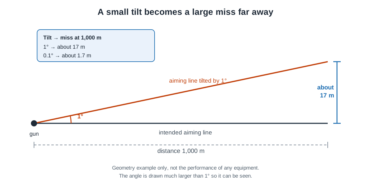
Basic trigonometry shows that if the aiming line tilts by 1°, it is about 17 m off at 1,000 m. Even a 0.1° tilt puts it about 1.7 m off at 1,000 m. These numbers are not the performance of any equipment. They only show how tilt and distance work together.
On a moving tank the tilt never sits still. Even while crossing a single bump, the front rises, drops and then leans another way. So the correction is not made once and finished.
It has to keep going for as long as the shaking does. The same geometry of angle and distance, seen from the laser beam side, is covered in the article on laser beam pointing and tracking. That article uses the milliradian (mrad), a unit far smaller than a degree.
The gyroscope: a spinning top that holds a direction
A gyroscope is a kind of top. When it spins fast, its inertia makes it stable, which is Newton's first law, the law of inertia from high school physics. As a result, the axis of a gyroscope keeps pointing in one direction.
Rocket pioneer Robert Goddard used this property to guide his rockets. NASA's rocket teaching guide puts a gyroscope at the core of the control system Goddard built. If the rocket strayed from its course, the motion acted on the gyroscope's alignment. A linkage or electrical system tied to the gyroscope then sent the right corrections to movable fins.
The guide suggests a simple test: stand a long stick upright on your palm and try to keep it there. As soon as the stick starts to tip, your hand moves to follow it. In Goddard's rocket, a gyro picked up the tilt and a machine moved the fins, instead of a person's eyes and hand.
Inertial sensors include gyroscopes, which measure angular change, and accelerometers, which measure velocity change. They come in many forms, from single-axis devices to packages with three gyros set at right angles to each other. A package that combines such sensors is an inertial measurement unit (IMU).
Measure, compare, turn back
Now put the pieces together. When the hull moves, the gun turns with it. A sensor measures that turn. In the warship gun director above and the laser test setup below, that sensor was a gyro.
A controller compares the measured turn with the direction the gun should hold and works out the difference. A drive then turns the gun the opposite way by that amount.
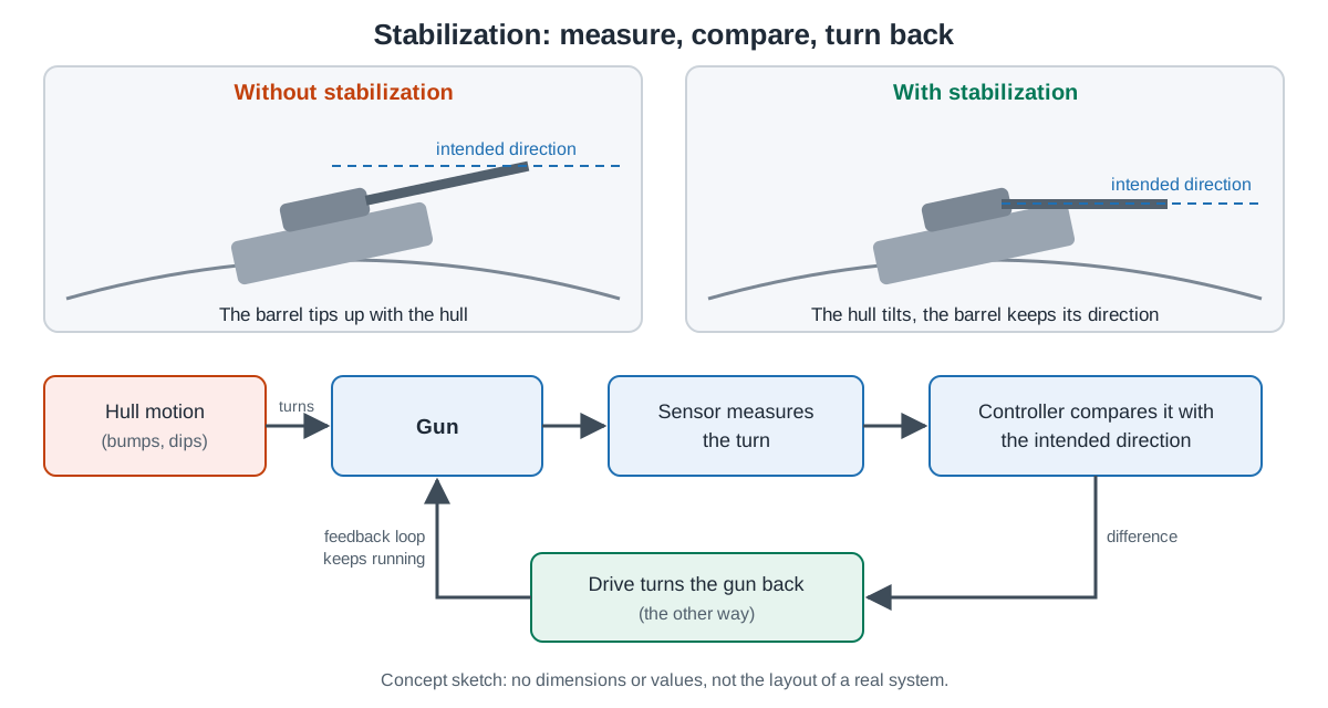
A loop that measures the result again and uses it for the next move is called feedback. As long as the shaking goes on, this loop keeps running. The drawing above shows only the main idea. A real system is tied in with sights, ballistic calculation and target tracking, and is far more complex.
Turning the turret also takes power. On the Sherman, the powered turret traverse drew on an auxiliary generator. With the engine off, the tank still kept its full ability to fight. South Korea's K1 tank uses an electro-hydraulic gun and turret drive.
Having the equipment did not always mean it was fully used. The Tank Museum adds that Sherman crews did not always make full use of the stabilizer, but the technology was there.
From the Second World War to today
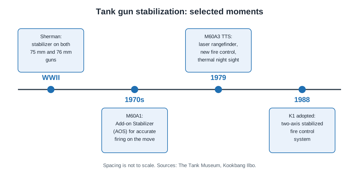
The starting point is the Sherman described above, with a stabilizer on both its 75 mm and its 76 mm guns. After that, stabilizers were improved side by side with gear for measuring range, seeing at night and computing fire.
The American M60 family is one example. The M60A1 was upgraded again and again during the 1970s. First came the Add-on Stabilizer (AOS), which let the tank shoot accurately while moving.
Next came an engine reliability upgrade and passive night viewing gear in place of the old infrared searchlight. The M60A3 TTS of 1979 followed, with a laser rangefinder, new fire control and a thermal sight for night use.
On the M60, the stabilizer, the rangefinder and the fire control system were improved one after another inside the same tank. The link between sensors and weapons is covered in more detail in "Fire-control systems".
South Korea's K1 tank was adopted as combat equipment for the Korean armed forces at a weapon system review on December 19, 1988. The approval came on the condition that some items be improved.
Kookbang Ilbo, the Korean defense daily, calls the K1's fire control a "two-axis stabilized fire control system." It is made up of the gunner's sight, the commander's sight, a ballistic computer and other parts. It can observe by day and by night.
Stabilization is not only for tanks. According to the Agency for Defense Development, the K21 infantry fighting vehicle carries a stabilized 40 mm automatic cannon and, as an option, anti-tank guided missiles. Wherever a weapon is meant to be used from a moving vehicle, the same problem comes along.
Where this meets lasers: a beam on a shaking mount
Holding one direction on a shaking mount is also a problem for laser weapons. A 2010 SPIE conference paper by researchers from South Korea's Agency for Defense Development and the U.S. Naval Postgraduate School names two key technologies for high energy laser systems. One is pointing the beam precisely.
The other is rejecting, over a wide bandwidth, the jitter caused by platform vibration. Motion of the platform and of optical parts causes optical jitter, which hurts pointing accuracy and blurs images.
The paper's test setup has a structure much like tank gun stabilization. On the wide field of view side, the control system steadies the azimuth and elevation of a telescope gimbal. It is meant to keep the line of sight (LOS) toward the target steady when outside forces push it.
An inner loop uses feedback from rate gyros to fight the shaking. An outer loop uses camera images to keep the line of sight on the target center.
There is a difference, too. The setup splits the work in two. The gimbal handles the large motions. On the narrow field of view side, a camera working with a fast steering mirror (FSM) handles fine tracking and pointing of the beam on the target.
It is not easy. In the same tests, several resonances in the azimuth axis caused a significant drop in tracking performance. The paper also notes that a high energy laser system must correct for disturbances that change over time, which may call for adaptive control. From the Sherman's stabilizer to the fast steering mirror of a laser test setup, the loop of measuring, comparing and turning back keeps the same shape.
What to read next
- Main battle tanks: is it all about the gun?: looks at firepower, where stabilization belongs, alongside protection and mobility.
- Fire-control systems: linking sensors and weapons: shows how tracking, prediction and correction build on a steady line of sight.
- Gimbals, pointing and tracking: holding the beam on one spot: looks at the same problem in more detail from the laser beam pointing side.