Stand in an open field on a night with no moon, and you can barely see the path in front of you. Even so, the night is not completely dark. Faint light, such as starlight, still falls on the ground.
Night vision goggles make that faint light bright enough for the eye to use. The part that does this is the image intensifier tube. This article follows how light turns into electrons inside the tube and back into light. It also looks at why the picture is green, what the generation names mean, and which limits public sources describe.
Amplifying light versus seeing heat
There are two main ways to see in the dark. Image intensification makes the light that is already around brighter. Thermal imaging picks up differences in the heat that an object and its background give off. The U.S. Army calls these the two foundational capabilities for seeing in the dark, and notes that image intensification came first, in the earliest scopes.
The two methods collect different light. Thermal imaging collects the heat that objects give off on their own, which is infrared radiation. Image intensification collects visible light reflected from objects and the near-infrared light just beyond it. An image intensifier is easy to recognize by the green picture it makes.
Thermal imaging is covered in "Thermal Imaging Sights: Seeing Heat in the Dark," and equipment that looks for the heat of aircraft is covered in Infrared search and track.
Light into electrons: the photocathode
At the front of an image intensifier tube sits the objective lens. The lens focuses the incoming light onto a surface called the photocathode. A photocathode responds to visible light and to near-infrared light as well.
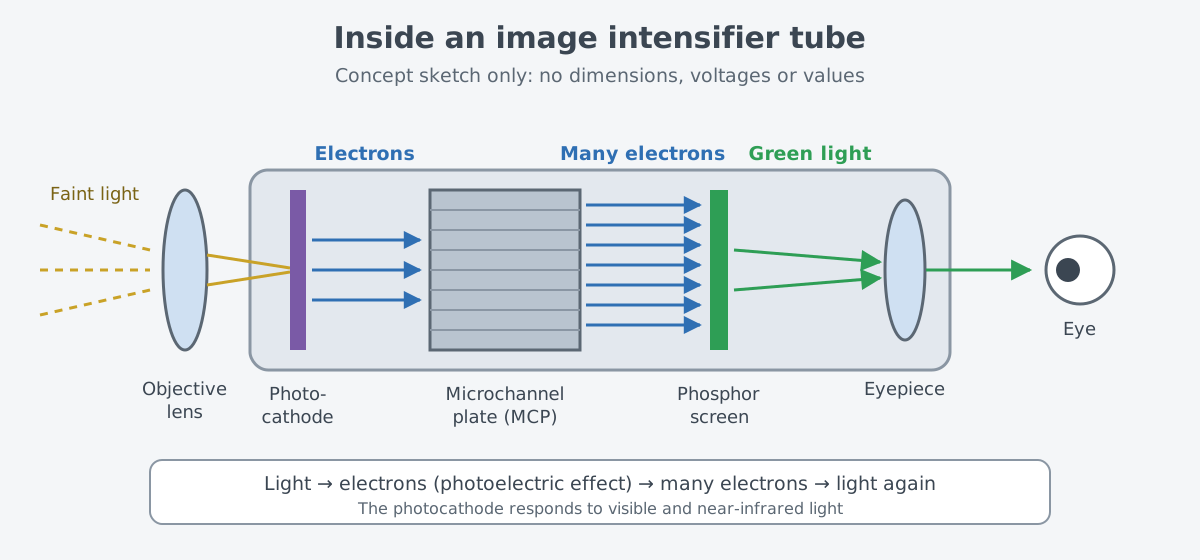
What happens at the photocathode is the photoelectric effect from physics class. Shine light of short enough wavelength on a metal surface, and the surface absorbs it and gives off electrons. Light arrives as particles called photons, and each photon hands all of its energy to a single electron.
The number of electrons that leave the photocathode rises in step with the amount of light that hits it. The tube then multiplies those electrons before they reach the screen, and that is what makes the picture brighter.
Multiplying electrons: the microchannel plate
The part that multiplies the electrons is the microchannel plate (MCP). It is a thin disk made of a huge number of very fine glass tubes bundled side by side. Each tube is called a channel, and every channel works as its own electron multiplier.
When an electron strikes the inside wall of a channel, the wall releases secondary electrons. A voltage across the two ends of the channel pulls these electrons forward, and they hit the wall again and release still more. This repeats many times along the channel, so far more electrons come out of the exit than went in.
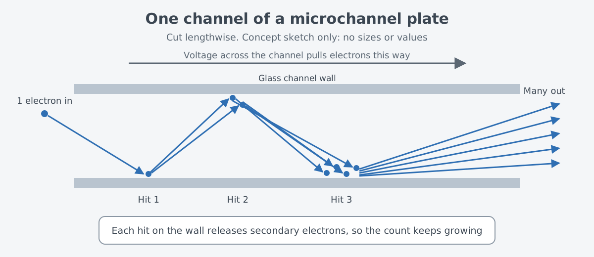
It is a bit like a snowball that grows as it rolls down a slope. In reality there is no slope. The electric field made by the voltage has to speed the electrons up so that they hit the wall again, and each hit frees more electrons.
Electrons are not the only thing produced inside a channel; ions form too. A photomultiplier tube handbook describes a thin film called an ion barrier on the input side of the MCP. It stops those ions from flying back to the photocathode. In image intensifiers, this film arrived with Generation III tubes.
Each tube also has automatic gain control. When the scene gets brighter, it lowers the tube's sensitivity, which protects the electron multiplier from overworking and being damaged by strong light.
Back to light: the phosphor screen and the green image
The multiplied electrons strike a phosphor screen at the back end of the tube. A phosphor gives off light when electrons hit it, and the number and speed of those electrons set how much light comes out. The scene that was faint at the front shows up here as a bright picture again.
The viewer looks at this screen through an eyepiece. In ANVIS, a night vision goggle used by U.S. military aviators, the eyepieces form virtual images of 18 mm phosphor screens and give a 40° field of view.
Why is the screen green? The human eye's daytime response peaks at about 555 nm, in the green part of the visible spectrum. A book from the U.S. Army Aeromedical Research Laboratory (USAARL) says it is no coincidence that many display phosphors are green or greenish yellow. Its example is ANVIS, which uses P20 and P22 green phosphors.
From searchlights to Generation III
Night viewing equipment existed in World War II. Very large infrared searchlights were mounted on the back of trucks. They swept the dark sky with infrared light, so they eventually became a liability that could give away the Allies' position. The United States, Germany, and Russia used image converter tubes in combat, mainly in rifle and sniper scopes.
In principle, an image converter tube could amplify night light such as starlight. In practice it was so insensitive that it nearly always needed infrared lighting alongside it, such as a searchlight fitted with a filter that blocked visible light. These tubes were the ancestors of today's image intensifiers.
In 1965, the night vision camera that U.S. Army researchers were working with was a heavy box that needed a 20-minute exposure. It was not portable, and it needed a fair amount of light from the stars and the moon to produce one grainy image.
Around the same time, the Army's Night Vision Laboratory, with Dr. Robert S. Wiseman as its founding director, developed image intensifiers in-house from 1965 to 1968. According to an Army article, the Department of Defense received more than a million image intensifiers over the next 50 years.
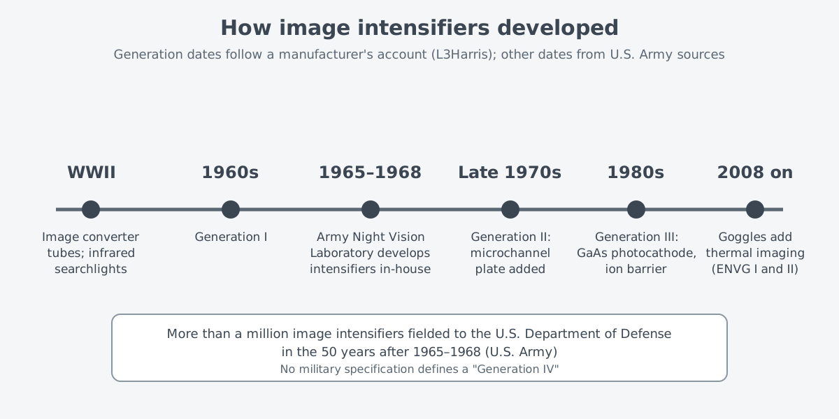
The generation names rest on U.S. military definitions. According to an account by L3Harris, a maker of image intensifier tubes, Generation I tubes appeared in the 1960s. Generation II tubes followed in the late 1970s, with a better photocathode and the new microchannel plate. Generation III tubes in the 1980s introduced a gallium arsenide (GaAs) photocathode and an ion barrier on the MCP, and no military specification defines a "Generation IV."
A 1992 report from the U.S. Army Research Institute (ARI) also shows the difference between generations. The AN/PVS-5, the first night vision goggle used by Army pilots, was originally designed for ground vehicle drivers and uses Generation II tubes. ANVIS, which uses Generation III tubes, responds more strongly to red and near-infrared light, the kind typical of night illumination. Semiconductor photocathodes such as gallium arsenide are highly sensitive from the ultraviolet through the near infrared.
Limits: it needs light, and it fools the eye
An image intensifier only amplifies light that is already there; it does not make any. Image intensifiers of the 1970s needed ambient light and clear air, and in overcast skies or smoke and dust they were effectively blind. World War II converter tubes responded only up to about 1.3 µm and could not see the heat that objects give off on their own.
A brighter picture is still not as sharp as normal sight. The ARI report gives 20/50 as the best acuity possible with the AN/PVS-5, and 20/40 for ANVIS under ideal conditions, adding that acuity usually drops in the field. In one study, ANVIS acuity under starlight fell to worse than 20/80.
The sense of distance also suffers. Night vision goggles nearly remove the depth that comes from using two eyes, so depth perception becomes similar to seeing with one eye. The picture has no color differences, and differences in shade, detail, and texture shrink.
The narrow 40° field of view is another limit. Fewer objects are visible at once, which makes it harder to judge distance by comparing the sizes of known objects. The tubes themselves also grow less sensitive with age.
Some newer equipment combines both methods. According to a 2018 Army article, most soldiers use the PVS-14, a one-eyed goggle based on image intensification. Some have received the Enhanced Night Vision Goggle I and II, first fielded in small numbers in 2008. The main difference between them is the added thermal imaging.
Where this meets lasers: the energy of one photon
The photoelectric effect has a threshold. The energy of a photon is set by its frequency alone, and every metal surface has a cut-off frequency below which light produces no photocurrent. A lower frequency means a longer wavelength, and the cut-off frequency differs from material to material.
So each photocathode responds to its own range of light. World War II converter tubes responded up to about 1.3 µm, while ANVIS, with Generation III tubes, responds more strongly to red and near-infrared. The idea that wavelength changes how light meets matter continues on the laser side in Why wavelength matters: visible and invisible light.
What to read next
- Thermal Imaging Sights: Seeing Heat in the Dark: another way to see, using heat when there is no light at all.
- Infrared search and track: seeing aircraft without emitting: equipment that uses infrared to find aircraft in the sky.
- Why wavelength matters: visible and invisible light: the link between photon energy and wavelength, seen from the laser side.