When a pilot moves the stick, movable panels on the wings and tail move with it. In the past, cables and rods linked the two. According to NASA, however, electric flight controls are now standard on almost every modern high-performance jet, as well as on military and civilian transport aircraft. The stick's movement becomes an electrical signal that goes to a computer, and the computer decides how to move those panels.
This approach is called fly-by-wire (FBW). This article traces how flight controls moved from cables to wires and why a computer ended up in the middle. It draws on the Federal Aviation Administration (FAA) pilot handbook and NASA test aircraft records.
Cables and rods to the control surfaces
An airplane changes direction with movable panels on its wings and tail, called control surfaces. The ailerons, elevator and rudder form the primary controls. They are needed to control the aircraft safely in flight.
Early aircraft used mechanical controls. Rods, cables, pulleys and sometimes chains carried the pilot's force straight to the control surfaces. Think of a bicycle brake cable.
The difference is that in an airplane, the pilot's arm works directly against the force of the air. Small general aviation and sport aircraft, where the air loads stay modest, still use this design today.
As aircraft grew larger and faster, the air loads on the control surfaces rose sharply. Muscle alone was no longer enough, and hydromechanical controls appeared, with a hydraulic circuit added to the mechanical one. NASA's F-8 fact sheet notes that before long, every big or high-performance airplane relied on them.
Wires instead of cables, a computer in between
The FAA handbook describes fly-by-wire as a flight control system in which an electrical link takes the place of the mechanical one between the cockpit controls and the control surfaces. The surfaces are driven through electric motors, digital computers or fiber optic cables. When a digital computer is part of the loop, the system is called digital fly-by-wire (DFBW).
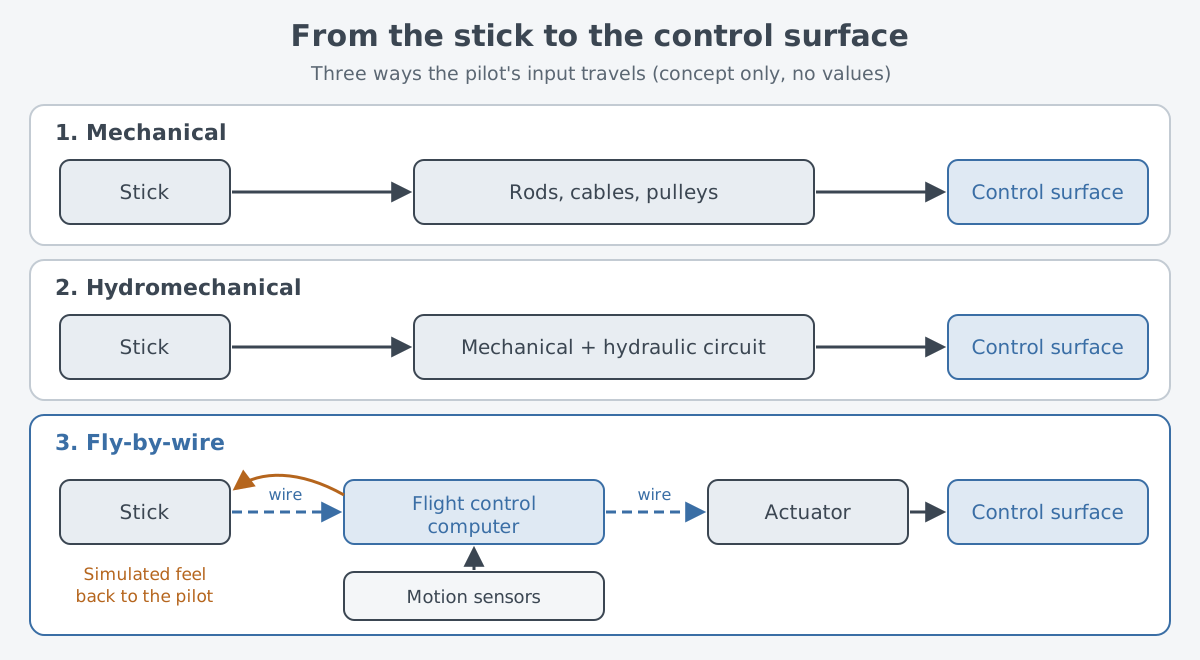
Without cables, the pilot no longer feels the air pushing back through the stick. So a fly-by-wire system simulates that feel and feeds it back to the pilot. The autopilot is not a separate add-on either. It is built into the system as one of its parts.
What do wires bring? NASA sums it up this way: aircraft gain safety, agility and efficiency. Redundant channels add safety, and on military aircraft, wires stand up to combat damage better than the hydraulic tubing they took over from.
A computer can command adjustments more often than a human pilot. The system is lighter and smaller than hydraulic controls and needs less maintenance. For airliners, it can also give a smoother ride than a pilot alone could.
Stability: the tendency to return
To see why the computer matters so much, start with stability. An aircraft's stability is its built-in tendency to correct a disturbance and return to, or keep to, its original flight path. It is mostly set by the design.
Static stability looks at the first tendency right after a disturbance. If the aircraft tends to return to its original balance, it has positive static stability. If it tends to stay in the new condition, it is neutral. If it tends to keep moving away, it has negative static stability.
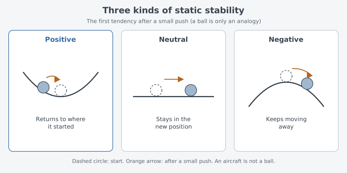
A ball in a bowl, a ball on a flat board and a ball on top of an upside-down bowl make the three cases easy to tell apart. A real aircraft is not set by its shape alone, though. Where its center of gravity sits also changes how stable it is.
Stability in the nose-up and nose-down direction is called longitudinal stability. The FAA handbook says that an aircraft unstable in this direction tends to dive or climb more and more steeply, and can even stall. That makes it hard to handle and at times dangerous. As the center of gravity moves rearward, the aircraft becomes less stable, and past a certain point it becomes unstable.
An aircraft made unstable on purpose
A stable airplane is safe, but stability has a price. With cable and hydraulic controls, designers needed built-in flight stability, and that limited the shapes they could choose. NASA explains that computers let designers drop features that made a plane more stable and therefore harder to maneuver. Replacing cables with wires also gives more freedom in how big the tail surfaces and wings are and where they go.
The X-29, flown at NASA's Ames-Dryden Flight Research Facility from 1984 to 1992, is an extreme example. Its wings swept forward, and its canards, horizontal surfaces that control pitch, sat ahead of the wings rather than at the tail. This layout was highly unstable. Sensors tracked attitude, speed and other flight conditions, and the computers kept adjusting the control surfaces to create artificial stability.
Why build it unstable at all? A conventional airplane balances the lift on its wing against a downward load on its tail, and that balance costs drag. The X-29 reduced its static stability on purpose to avoid this drag penalty.
Phase 1 flights showed the control laws and surfaces were enough to give this aircraft artificial stability with good handling for the pilots. However, the X-29 did not show the overall drag reduction that earlier studies had predicted. In total, the X-29s flew 422 research missions.
The first flight: NASA's F-8 testbed
Flying on wires and a computer alone was not an obvious step. In the late 1960s, engineers at NASA's Dryden Flight Research Center began talking about converting an aircraft into a test platform for digital fly-by-wire. At NASA Headquarters, Neil Armstrong of Apollo 11 supported the idea and backed transferring a Navy F-8C Crusader to NASA. It received the tail number "NASA 802."
On this F-8, wiring that ran from the cockpit stick out to the wing and tail surfaces took the place of every mechanical link. Its core came from Apollo: an off-the-shelf backup unit of the spacecraft's digital flight computer, plus an inertial sensing unit. On May 25, 1972, this F-8 flew with its flight relying entirely on electronic flight controls, something no aircraft had done before. Gary Krier was at the controls.
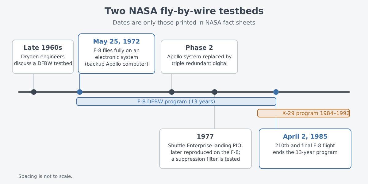
The testbed also helped solve new problems. A pilot induced oscillation (PIO) occurs when a pilot's inputs are too strong and the aircraft keeps swinging back and forth. In 1977, a PIO developed as the prototype Space Shuttle Enterprise settled onto the runway. NASA reproduced the problem on the F-8, then built and tested a filter to suppress it.
The program ran for 13 years. The 210th and final flight was on April 2, 1985.
The side-mounted control stick of the F-16 fighter was also tried out on NASA 802. NASA describes the F-16 as the earliest high-performance U.S. aircraft equipped with DFBW. Digital fly-by-wire, it adds, is now found on aircraft as different as the F/A-18 and the Boeing 777, as well as on the space shuttles.
Layers against failure
Putting a computer between the stick and the control surfaces raises a new worry. What happens if the computer stops? That is why fly-by-wire was built in layers from the start.
In Phase 1, a second fly-by-wire system on the F-8 stood by in case the Apollo computer failed. It never had to be used in flight. In Phase 2, a joint effort with NASA's Langley Research Center, the Apollo setup gave way to a digital system with three redundant channels. If a failure occurred, backup computers could keep the work going.
One worry still remains. A common software fault can stop all three channels at once. On the F-8, NASA also demonstrated a software backup, the Resident Backup System, as a way to survive such faults.
The X-29 followed the same idea. It carried three digital flight control computers, each paired with an analog backup. When one digital unit failed, the other two carried on, and with two failed, the system switched to analog mode. NASA's fact sheet puts the chance of a total system failure in the X-29 on a par with that of a mechanical failure in an ordinary control system.
Where this meets lasers: measure and correct
At the core of fly-by-wire is a loop. Sensors measure the current state, and a computer reads those values and keeps correcting the control surfaces. Even an aircraft like the X-29, which would drift away on its own, is held in place by this loop.
The same idea shows up on the laser side. The small mirror that keeps a laser beam steady takes the beam position measured by a sensor, tilts the mirror, and measures the result again. This feedback loop is covered in Fast steering mirrors: small, quick mirrors that cancel shake. One loop holds an airplane and the other holds light, but both repeat the same cycle of measuring and correcting.
What to read next
- Thrust vectoring: steering with the engine: how engine exhaust turns the aircraft when the angle of attack is high and control surfaces lose their grip.
- Stealth aircraft: truly invisible?: what shape design changes besides flight.
- Fast steering mirrors: small, quick mirrors that cancel shake: the feedback loop that holds a laser beam steady.