Suppose two companies both print "M² < 1.1" on their laser datasheets. Can you compare the two numbers directly? One company might define beam width as the point where brightness falls to a set fraction of the peak. If the other uses a different definition, the same beam could give different M² values.
That is why the method for measuring M² is fixed in an international standard. This note sets out what that standard, the ISO 11146 set, covers and how the big picture of the measurement is laid down. It uses the public summaries and a manufacturer's description. What the beam quality figure M² means comes first in "Beam quality: M², divergence and brightness".
The same M² needs the same method
M² compares the product of a real beam's waist diameter and divergence angle with the same product for an ideal Gaussian beam. The result depends on how the two quantities in that product, beam width and divergence, are defined and where they are measured.
A standard ties this "how" and "where" to one agreed method. With the same agreement, values measured by different companies or labs can be compared. The other way round, if a datasheet does not say which agreement it followed, the number alone is hard to compare.
The ISO 11146 set: what each document covers
The laser beam measurement standard of the International Organization for Standardization (ISO) comes as three documents. The formal titles are long, but they say the same thing. They are test methods for the beam widths (diameter), divergence angles and beam propagation ratios of laser beams, and the beam propagation ratio is M².
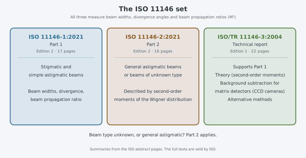
Part 1 (ISO 11146-1:2021) is the second edition, published in July 2021, with 17 pages. It applies only to stigmatic and simple astigmatic beams. Astigmatism is when a beam focuses and spreads differently in different directions, and Part 1 handles the simpler cases. The ISO summary says that if the beam type is unknown, or the beam is general astigmatic, Part 2 applies.
Part 2 (ISO 11146-2:2021) is a second edition from the same time, with 16 pages. It covers general astigmatic beams and beams of unknown type. Its summary says it describes beams by a statistical quantity, the second-order moments of the Wigner distribution. They stand in for quantities like width and divergence, and the summary notes that the two are closely linked.
The third is technical report ISO/TR 11146-3:2004, published in February 2004, with 22 pages. It supports Part 1 with a theory based on second-order moments, and gives details on removing the background correctly when cameras and other array detectors are used. It also offers other methods for cases where such detectors are missing or do not work well.
Parts 1 and 2 both replaced 2005 editions. ISO reviews each standard every five years, so it is worth checking which edition a datasheet or report followed. ISO sells the full texts of all three, and the summary pages show the scope and a preview button.
How beam width is defined
A beam has no knife-sharp edge. It is bright in the middle and fades gradually outward, so you have to decide where the beam ends before you get a width.
Two names need to be kept apart here: the summaries of Parts 2 and 3 talk about the second-order moments of the Wigner distribution, a mathematical description of a beam. Part 2 uses them to describe beams. The formulas that turn these moments into physical quantities such as beam width are in Part 3. The public summary of Part 1 does not say in what words Part 1 defines beam width.
What a camera-type beam profiler actually works out is a second-moment width taken from the intensity of one cross-section. A white paper from the beam profiler maker Ophir calls this value D4σ. To keep it apart from the Wigner moments, this note calls it the "D4σ width." The kinds of instrument are covered in "Measuring light: power meters, beam profilers, spectrum analyzers".
This second-moment width counts not only the middle of the beam but also the signal out in its edges, often called the wings. That is why noise lying in the wings can throw the width off. In the white paper's models, the second-moment width swung widely around its true value as a beam dimmed and its signal-to-noise ratio fell. When more of the sensor was covered by the beam and real signal outweighed the noise in the wings, the values settled.
The same paper says a correct baseline is only part of the answer. Noise in the area around the beam also has to be removed to get an accurate second-moment width. According to the paper, the 2004 ISO/TR 11146-3 method isolated the beam inside an aperture three times the second-moment width. This is why Part 3 gives background subtraction its own treatment.
Measure at many positions, then fit a curve
A width measured at one position does not give M². You need to know where the narrowest point, the waist, is, how narrow it is there, and how much the beam opens up farther away.
Because the standard's full text is paid, the requirements in this section follow Ophir's own account of ISO 11146-1, written to describe its instrument. In that account, beam widths are taken at no fewer than 10 positions along the propagation direction (z). Roughly half sit no more than one Rayleigh length from the waist; the others lie farther out than two Rayleigh lengths. The Rayleigh length is the stretch near the waist where the beam barely widens and stays narrow.
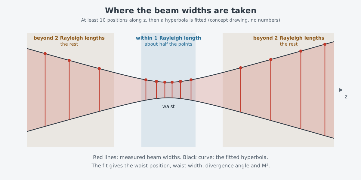
A hyperbola is then fitted to the points along the direction of travel, and that single curve gives the waist position, waist width, divergence angle and M² together. Ophir writes that the details of this fit are in section 9 of Part 1, and that M² is defined in section 3.16.2.
Splitting the points between the two zones lets a single curve capture both the position and size of the waist and how much the beam opens up far away. The M² article describes it as "at least 5 measurements near the waist and at least 5 far away." That is the same requirement, written in a different way.
The section numbers also come from Ophir's account. The company explains that the filtering and background subtraction in its instrument follow ISO's advice, and that most of this processing belongs to sections 6.4 and 6.5 of Part 1. In Part 1, section 5 covers the test principles and section 6 the measurement setup and equipment.
Reading an M² figure on a datasheet
First, see which standard was followed. Check whether it says "measured according to ISO 11146," and whether that means Part 1 or Part 2. If nothing is said, treat the number as a rough guide only.
Second, see whether the measurement met the requirements. Ophir explains that its software labels a result as ISO only when the fitting rule is satisfied, and uses a plain direct calculation instead if the curve cannot be fitted. Values from the same instrument can mean different things depending on whether the requirement was met.
Third, see whether separate values are given for the two directions. Part 1 handles beams with simple astigmatism, so a beam whose cross-section is not round can have different values in each direction. If only one value is given, find out which direction it refers to, and see whether the measurement conditions (power, wavelength) are stated.
What to read next
- "Beam quality: M², divergence and brightness": what the M² measured here is, and how it links to brightness.
- "Measuring light: power meters, beam profilers, spectrum analyzers": the camera and slit instruments used to measure beam width.