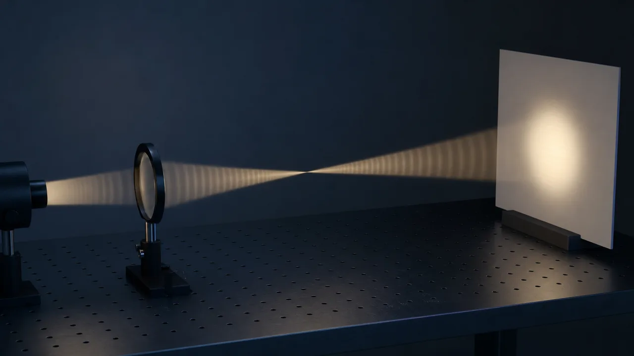
How much wider does a beam get after 1 m, or after 1 km? On a lab bench you can hold up a sheet of paper and look. Before a device is built, or over a distance you cannot measure, you have to estimate it by calculation first. Working out how light changes shape as it travels through space is called a beam propagation calculation.
The Gaussian beam, the beam waist, the Rayleigh length and the beam divergence first came up in Why a beam spreads: divergence, focus and aperture. This time the article follows the thinking behind those words.
The starting point is adding up the fields of light together with their phase. Diffraction, the spreading of light beyond a narrow opening, is also explained with this kind of addition. From there it takes the Gaussian beam as a shortcut and ends with estimating how much a beam spreads using one Rayleigh length. Last come the cases where that estimate does not work.
Add fields, not intensities: superposition and phase
Light is a wave in which an electric field and a magnetic field oscillate together. In linear optics, the fields and their derivatives appear in the wave equation only to first order. That is why the superposition principle holds. Any combination of solutions, added together, is again a solution, so complicated light can be seen as a sum of simple waves.
There is one thing to watch when adding. What you add are fields, not intensities. Intensities generally do not simply add; they add only when the two beams cannot interfere. That happens when their polarizations are perpendicular to each other, or when the two beams are fully incoherent.
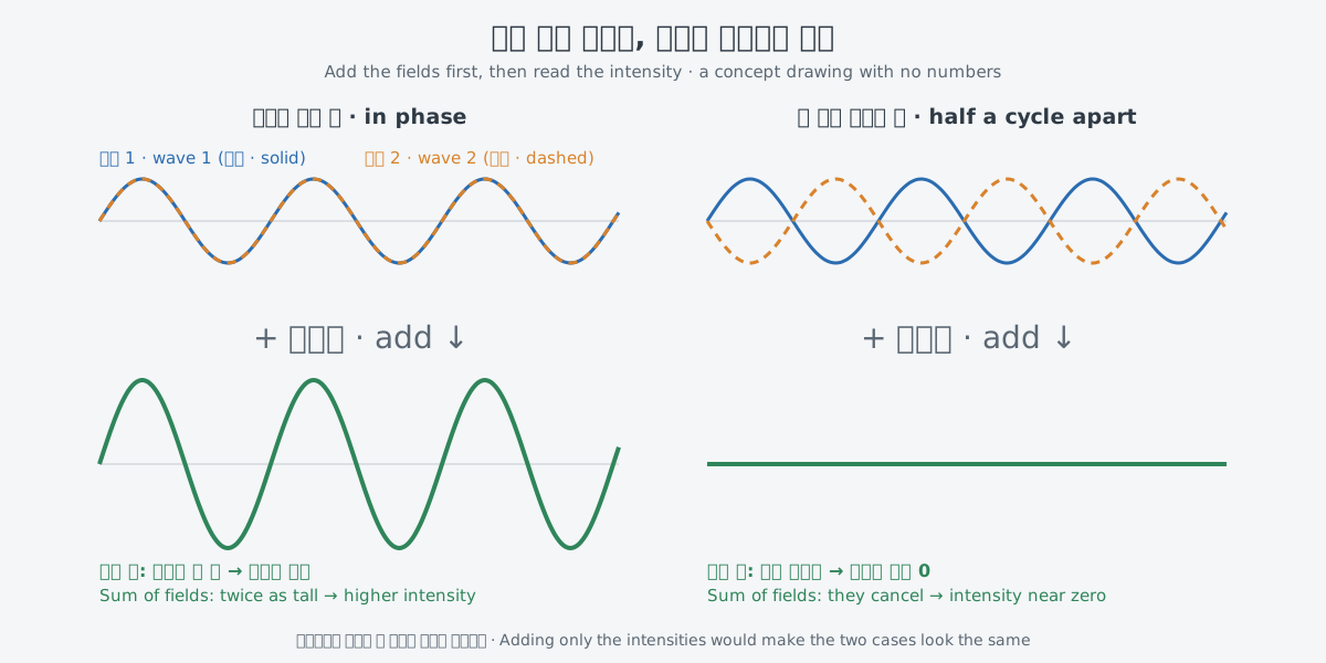
So a calculation has to carry the phase of the light, not just its intensity. The same two waves give a larger summed field when they are in phase. When they are half a cycle apart, crest meets trough and they cancel. This difference is the interference seen in "Interference and diffraction".
Complex numbers are handy for handling size and phase at once. Written in complex notation, a plane wave has a single complex amplitude that holds both its size and its phase. Complex notation means exactly the same as the real form, but the math becomes much easier.
Wavefronts and the Huygens principle: finding the next shape by addition
Joining points that have the same phase gives a wavefront. In an isotropic material, where the refractive index does not depend on direction, the wavefront is always perpendicular to the direction the light travels.
How, then, do you get the wavefront a moment later from the present one? The Huygens principle, seen in Interference and diffraction: how light adds up and spreads, gives the frame of the answer. Every point of an advancing wavefront becomes the source of new secondary waves, and the new wavefront forms where those secondary waves line up.
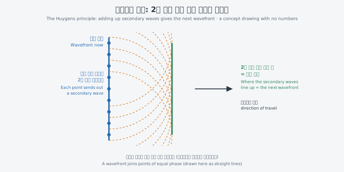
Put in the language of calculation, it goes like this. Suppose you know the size and phase of the field at each point of the present wavefront. Adding the secondary waves from all those points, phases included, gives the field a little farther on. That article pictured diffraction with the same picture.
Seeing a beam as plane waves traveling in many directions
There is another way to split a beam. It is easier to see on the time side first. A Fourier transform splits a signal that changes in time into frequency components. For an ultrashort laser pulse, each of those components is a plane wave with a different frequency.
A similar description exists for a lens. A lens makes a Fourier transform of the incoming wave in its focal plane. A plane wave arriving at a particular angle gathers at one fixed place on the focal plane, a focal length f from the lens. A plane wave at a different angle goes to a different place.
Reading the two descriptions together suggests a similar picture in space. A pulse is seen as a sum of plane waves with different frequencies. In the same way, a beam can be seen as a sum of plane waves traveling in slightly different directions. The lens, in effect, spreads those directions out as places on the focal plane.
The pairing carries over to spreading. One passage of the textbook names pulse spreading by dispersion and beam spreading by diffraction side by side. In reality the two differ: the components of a pulse differ in color, while those of a beam differ in direction. Dispersion, which stretches a pulse, and diffraction, which widens a beam, are also different effects.
The Gaussian beam: a shape that keeps the calculation short
When a beam has the shape of a Gaussian beam, the calculation gets much shorter. A Gaussian beam traveling in the z direction can be approximated by a parabolic wave in the paraxial approximation, which handles only light close to the axis.
The beam is then described by its waist radius w₀ and the beam radius w(z) at each place. The distance over which the beam stays narrow near the waist is measured by the Rayleigh length L.
L = π n₀ w₀² / λ₀
Here λ₀ is the wavelength of the light, and n₀ is the refractive index at that wavelength. For estimates in air, set n₀ to 1. Two features matter later: the waist radius enters squared, and the wavelength sits in the denominator.
A beam passing through lenses and empty space can also be followed with a few values. The textbook gives each thin lens and each stretch of material of fixed length an ABCD matrix, a table with four entries. The width and divergence of the beam are bundled into a single value called the q parameter.
The output beam of a diode array with low spatial coherence can still be modeled with Gaussian beam optics using a modified wavelength. In other words, light with such low spatial coherence can still be estimated within the Gaussian beam framework.
How to estimate: compare the distance with the Rayleigh length
Now back to the opening question. To estimate how much a beam widens over some distance, the yardstick is the Rayleigh length L. Comparing the distance z from the waist with L tells you which zone the beam is in.
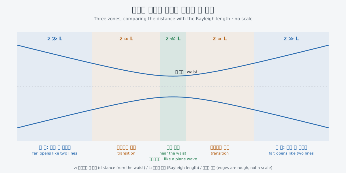
When z is much shorter than L, the beam is near the waist. Close to the waist, a Gaussian beam can be treated as a plane wave. The textbook uses this approximation for a measurement inside a very short crystal. In this zone you can start the calculation by taking the beam width as the waist width.
When z is much longer than L, the beam is far away. As shown in "Why a beam spreads", the edges of the beam there are treated as two nearly straight lines. The widening is judged by the divergence, the angle between those lines. Around L is the stretch where the two pictures join.
Try some numbers. Take a waist radius of 5 mm and calculate with the Rayleigh length formula. L comes out at about 157 m for a wavelength of 0.5 µm, about 78.5 m at 1 µm and about 7.85 m at 10 µm. With the same waist, a wavelength ten times longer makes the narrow stretch one tenth as long.
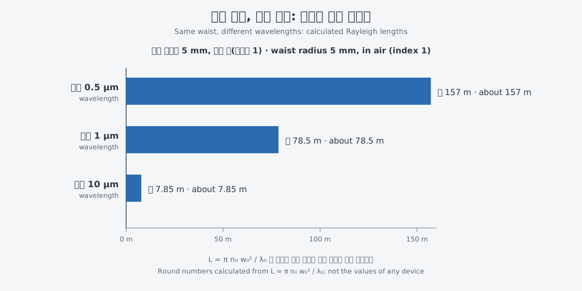
Take the middle row again: a beam at 1 µm with L of about 78.5 m. By calculation, 1 m is about one eightieth of L, so it falls in the zone near the waist. 1 km is about 13 times L, so it falls in the far zone. At the first distance you can keep the starting width, and at the second you have to reason with the divergence.
These are round numbers chosen to show the principle, not the values of any device. Atmospheric effects are not included either. The order of the estimate is short. Find L from the waist radius and the wavelength, compare the distance you care about with L, and pick the picture for that zone.
Where the simple picture breaks down
While light passes through a material, diffraction is not the only thing that changes the beam. In the propagation equation for a pulse, the envelope of the light changes because of absorption or gain, dispersion, diffraction and nonlinearities. The estimate above looks at only one of these, diffraction.
One example is light so strong that the material itself gathers the beam like a lens. In a long Kerr material with strong self-focusing of this kind, the beam diameter changes along the way. The material then has to be divided into thin slices, with the focusing effect readjusted to the new beam radius slice after slice. This is one form of a beam propagation calculation that does not end with a single formula.
With even stronger light, the Rayleigh length yardstick itself can stop fitting. A strand of light called a filament keeps a narrow diameter well beyond the normal Rayleigh range of a Gaussian beam. Even with the same waist, such light cannot be estimated with the three-zone picture above.
You also have to ask how close a real beam is to an ideal Gaussian beam. The light of the high-power diode arrays mentioned above is an example of light with low beam quality. The values that measure beam quality come in the next article.
What to read next
- "Beam quality: M², divergence and brightness": continues with the values that measure how far a real beam is from an ideal Gaussian beam.
- "A look at openly available calculation tools": looks at public tools for trying beam propagation calculations like these.
- "Why lasers are studied by calculation first": sets beam propagation beside amplification and heat calculations and shows how calculation and experiment work together.